
On a shutdown permit a closed valve is a request, not a guarantee. Positive isolation means a solid plate across the bore in a bolted joint — something a stuck wedge, a weeping seat or a well-meaning operator on the next shift cannot undo. Three devices deliver it: the blind flange, the spectacle blind and the spade-and-spacer pair. They answer to different standards, and choosing by whatever the store holds is how a plant restarts with a blank still bolted into a relief valve inlet.
Why a closed valve is not isolation
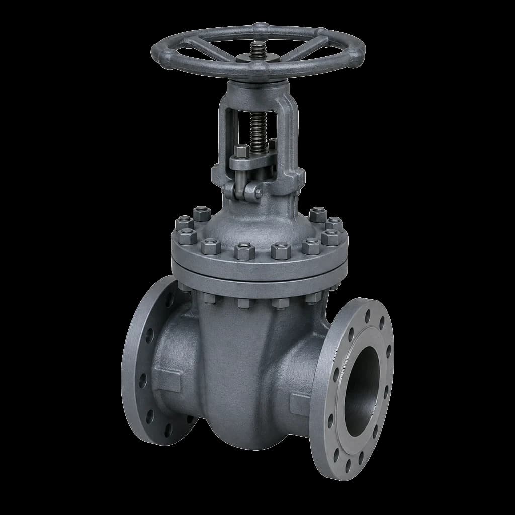
A valve is a mechanical seal with a published leakage allowance, not a barrier. API 598 permits zero visible leakage past a resilient seat but an explicit, size-proportional drop rate past a metal seat — a closed 12" metal-seated gate valve is allowed to pass, and that is the acceptance criterion at the works, before any service wear. Add solids on the seating face and a stem anybody can turn, and what you have is an operating control, not proof of isolation. Even a genuine double block and bleed arrangement only lets you monitor a barrier; it does not replace one for entry or hot work.
Indian statutory practice is unambiguous. Section 36 of the Factories Act 1948 bars entry into any chamber, tank or pipe that may hold dangerous fumes until a competent person certifies it safe, and permit systems built on OISD-STD-105 accept only a physical blind — installed, numbered and signed for — as the isolation behind that certificate. The logic is the same in a paper or sugar plant: if the permit says positive isolation, no valve position closes it out.
The three devices, and what each is actually for
Blind flange: a closure for an open end
A blind flange is a solid flange with no bore, dimensioned and rated alongside every other flange in ASME B16.5 for NPS 1/2 through 24 and B16.47 Series A and B for NPS 26 through 60; IS 6392 is the Indian equivalent where a project calls it out. It belongs at an open end: a line terminus, a spare nozzle, a manway. It is not an in-line isolation device: fitting one means dropping the spool beyond it, which turns a blinding job into a rigging job. Buy it in the mating flange's material group and facing, not a grade cheaper.
Spectacle blind: state you can read from grade
The figure-8, or spectacle blind, carries a solid disc and an open ring of equal thickness on one web. It lives permanently in the joint; changing state means slackening the bolts, spreading the flanges, swinging the plate through 180 degrees and re-torquing. It cannot be lost or misreported: an inspector at grade sees which half sits in the line. ASME B16.48 covers line blanks — spectacle blinds, paddle blanks and paddle spacers — through NPS 24 in Classes 150 to 2500.
Spade and spacer: the large-bore answer
Cut the figure-8 in two and you have the pair: the spade (paddle blank) is the solid disc on its own tab, the spacer (paddle spacer) the open ring — the same job in two pieces a fitter can carry separately. The spacer holds the flange gap constant, so bolt length, pipe stress and hanger settings never change between the blinded and open condition. The penalty is administrative: the idle half must be tagged with its line number and stored where the next shutdown team will find it.
| Device | Dimensional standard | Where it belongs | State visible from grade |
|---|---|---|---|
| Blind flange | ASME B16.5 / B16.47 (IS 6392) | Open ends, spare nozzles, manways, future tie-ins | Yes — the line simply ends |
| Spectacle blind | ASME B16.48 | In-line points blinded every shutdown, small and medium bore | Yes — the plate shows its own state |
| Spade + spacer | ASME B16.48 | Large bore, high class, or rarely changed in-line points | Only from the tab; needs tagging discipline |
Choosing between a spectacle blind and a spade
Two variables decide it: how heavy the plate gets, and how often you turn it. A Class 300 spectacle blind at NPS 24 is one plate too heavy to swing by hand, so changing state needs a crane, a clear radius and scaffold at height — none of which exists on a congested rack. Most owner specifications therefore cap spectacle blinds around NPS 10 to 12 and switch to spade-and-spacer above it, the cap falling as class rises. That is a house rule, not a code rule, so read the project piping specification.
- Blinded every shutdown: spectacle blind. The premium is recovered the first time nobody hunts for a missing half.
- Blinded once in the plant's life: spade and spacer — or a blind flange if the branch can be cut and closed for good.
- Large bore, elevated, tight rack: spade and spacer. Weight per lift is what makes the job safe, not total steel.
Blind flange thickness and pressure rating
For a blind flange the calculation is already done. A B16.5 blind carries the same pressure-temperature rating as any other flange of its class and material group — a Group 1.1 (A105) Class 150 flange is good for 19.6 bar at 38 degrees C and 13.8 bar at 200 degrees C, blind or not — and the thickness is tabulated. Get class, facing and material group right and nothing is left to compute.
Line blanks are different: a spade spans the gasket bore unsupported. B16.48 tabulates thicknesses for the standard sizes and classes; outside that table — an odd size, an unlisted material, a corrosion allowance the standard does not carry — thickness comes from ASME B31.3 para 304.5.3: t = d x sqrt(3P / 16SE) + c, where d is the inside diameter of the gasket for raised-face joints (the gasket pitch diameter for ring joints), P the design gauge pressure, S the allowable stress at design temperature, E the quality factor and c the corrosion and mechanical allowances. That number is not something to eyeball, and a plate flame-cut in the fab shop from whatever mild steel was lying about is not a blank. Insist on B16.48 marking on the tab and an EN 10204 3.1 certificate.
Where the blind is a hydrotest boundary, the governing pressure is the test pressure, not the design pressure — 1.5 times design under ASME B31.3, adjusted for the stress ratio at temperature. A valve should never end a test section either: seat and body are rated to the class, not to the test, and the damage does not always announce itself, as our note on hydrotest damage to valves sets out. Blind the boundary properly and the gate valves survive commissioning.
Gaskets, bolting and flange spread
An in-line blind turns one gasketed face into two and adds the blank thickness to the gap, so the studs that fitted the plain joint are short by that thickness plus a gasket. Both halves of a spectacle blind share one thickness and a spacer matches its spade, so a single longer set — A193 B7 / A194 2H, B7M/2HM in sour service — serves both states. Bag it with the blind, marked with the blind number. Gaskets are consumables here: a spiral-wound crushed once has spent its recovery, so fit two new ones at every change of state, matched to facing and rating as our spiral wound gasket selection guide sets out. A flat-face cast iron flange needs a full-face gasket and an FF blank: bolting a raised face against a flat-face casting is a crack waiting to happen.
The line blinding procedure and the blind register
Blinding is planned on paper weeks before the outage: mark up the P&IDs, number every point, write the register. In the field the sequence is depressurise, drain, purge or steam out, prove zero energy at the bleed before the joint is broken, slacken the far-side bolts first so the joint relieves away from the fitter, spread with jack screws or a flange spreader, fit the blank with new gaskets both sides, torque in the correct crossing pattern and hang the numbered tag. Removal is the same steps mirrored, and the register does not close until every number is signed back.
| Field | Why it is there |
|---|---|
| Blind number and P&ID reference | Ties the tag to the marked-up drawing |
| Line number, size, class, facing | Fixes blank, gasket and stud length |
| Type — blind flange, spectacle, spade | Tells the fitter what to carry |
| Location and access needs | Flags scaffold, crane and permit needs |
| Installed by, date, verified by | Two-person check; no signature, no isolation |
| Removed by, date, verified by | The line that releases the plant for start-up |
The dangerous failure is almost never an installed blind letting go. It is a blind left in — a blanked pump suction that runs the pump dry, a blanked vent that traps a vessel, and worst of all a blank in a relief valve inlet or outlet, which strips overpressure protection from a system nobody believes is unprotected. Hence the register with named signatures, the high-visibility paint, and the number stencilled on a tab that projects clear of the flange OD.
What to state on the shutdown enquiry
Shutdown enquiries fail on ambiguity. A line item reading "6 inch spectacle blind" will be quoted three ways and delivered wrong at least once. State the following — and the same depth for the valves and fittings going in during the same window.
- Size, class, facing (RF, FF or RTJ) and mating flange standard — B16.5, B16.47 Series A or B, or IS.
- Type explicitly: blind flange, spectacle blind, paddle blank, paddle spacer, or a blank-and-spacer set.
- Material — A105, A182 F304/F316 or a plate grade — plus corrosion allowance and any lining.
- Design pressure and temperature, and separately the hydrotest pressure if the blank is a test boundary.
- Documentation: EN 10204 3.1 or 3.2 MTC, dimensional report, and IBR paperwork where the blank sits in boiler-connected steam piping.
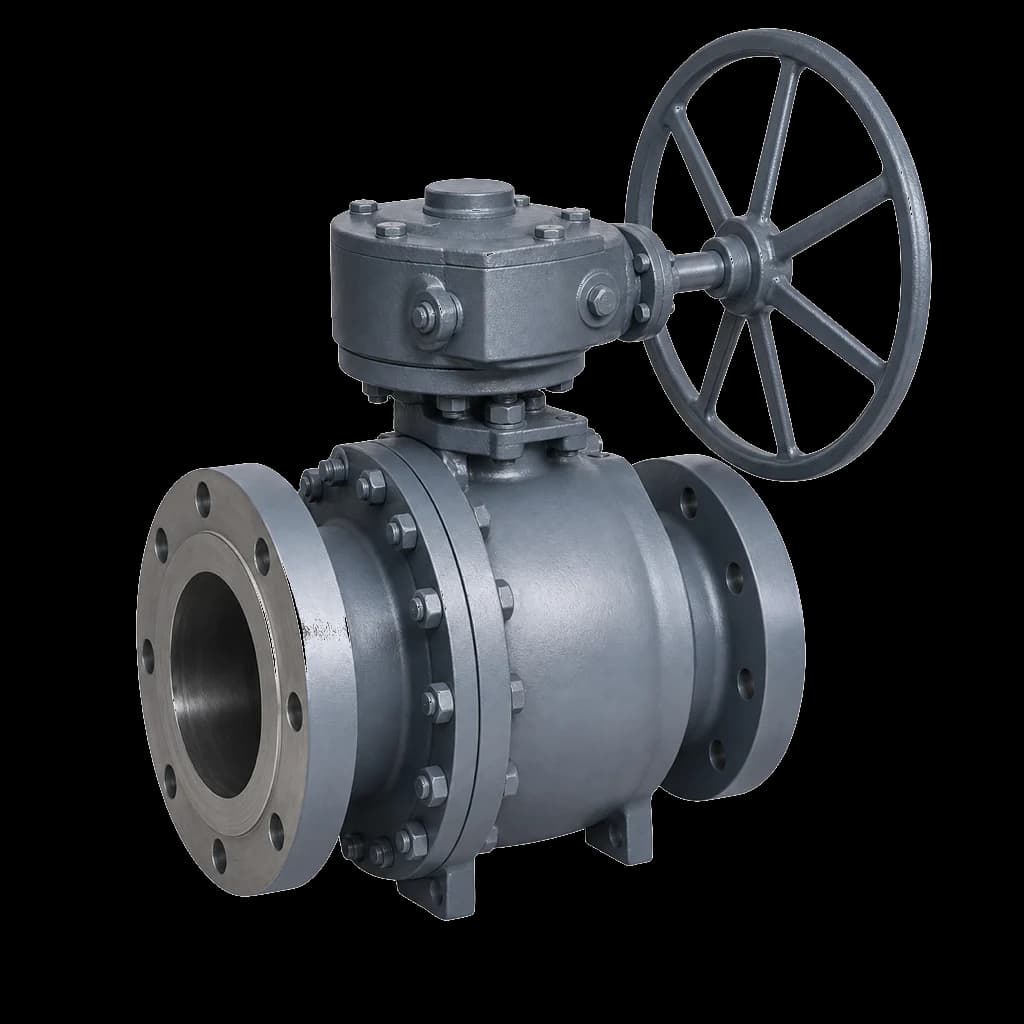
- The rest of the outage list in the same enquiry — replacement ball and gate valves, forged fittings for vents and drains, gaskets and studs — so one delivery lands against one dated window.