More valves are ruined between the goods-inward gate and first oil than are ever worn out in service. The hydrostatic test procedure and the flushing campaign around it are where most of that damage happens: a system test taken to 1.5 times design pressure across a closed soft seat, a gate valve cracked open to help the flushing along while weld slag jets across the seat face, a pallet of Class 300 valves stripped of their end caps in a laydown yard through a monsoon. None of it appears on the MTC. All of it appears as a passing leak at the first shutdown, and by then the warranty conversation is unwinnable.
What a hydrostatic test procedure actually loads
Three pressure tests appear in a valve's life and site teams routinely confuse them. Two arrive as paperwork; the third happens on your line.
Shell test and closure test, at the works
Under ASME B16.34 and API 598 the shell test proves the body, bonnet and bonnet joint at not less than 1.5 times the valve's 38 °C (100 °F) pressure rating, rounded up. For Class 150 carbon steel that rating is 19.6 bar (285 psi), so the shell test lands near 30 bar (450 psi); Class 300 is rated 51.1 bar (740 psi) and tests near 77 bar (1,125 psi). The closure or seat test is a far gentler load: the high-pressure closure test runs at about 1.1 times that same 38 °C rating, backed by a low-pressure air or inert gas test that catches leaks water would seal over. The API 598 valve testing guide sets out the mechanics and the allowable leakage rates.
Hold on to the ratio: the shell is proven at 1.5x, the seat only at 1.1x. Every commissioning mistake below is a version of forgetting it.
The system test is not a valve test
ASME B31.3 requires a hydrostatic leak test at not less than 1.5 times design pressure, held at least 10 minutes before joints are examined; B31.1 applies the same multiplier. That test proves your welds, flanged joints and threaded connections. It proves nothing about the valve — but it will happily destroy one left carrying the load.
| Test | Governing document | Pressure basis | What it actually proves |
|---|---|---|---|
| Valve shell test | API 598 / ASME B16.34 | 1.5 x the 38 °C class rating, rounded up | Body, bonnet and bonnet joint integrity |
| High-pressure closure test | API 598 | About 1.1 x the 38 °C class rating | Seat tightness with the valve shut |
| Low-pressure closure test | API 598 | Air or inert gas at low pressure | Seat leaks that water would mask |
| Process piping system test | ASME B31.3 | 1.5 x design pressure, 10 minutes minimum | Installed joints and welds, not seats |
| Power piping system test | ASME B31.1 | 1.5 x design pressure | Installed joints and welds |
| IBR steam piping | Indian Boiler Regulations | 1.5 x maximum permissible working pressure, witnessed | Statutory acceptance of the line |
| Buried water main | IS / CPHEEO practice | 1.5 x working pressure, held for hours | Joint tightness against an allowable make-up quantity |
Test pressure calculation, and the limit the seat sets
The hydrostatic test pressure calculation in B31.3 is not simply 1.5 times design pressure where the design temperature exceeds the test temperature. The minimum test pressure becomes 1.5 x design pressure x (allowable stress at test temperature / allowable stress at design temperature), with that stress ratio capped at 6.5, and the code lets you reduce a figure that would yield the piping. Two consequences bite in practice.
- The corrected test pressure can exceed the valve's own shell test pressure. A Class 150 line designed at the full 19.6 bar rating already tests at ~29.4 bar against a ~30 bar shell test. Add a stress correction and you are pressurising a body beyond anything the maker proved. Isolate it with a blind or a spool.
- Nothing licenses you to load a seat at test pressure. A valve used as the boundary of a test section is asked to hold 1.5x when it was proven at 1.1x. Metal-seated gate and globe valves usually survive. Soft seats often do not: PTFE and RPTFE cold-flow and take a permanent set, and PEEK, though far stiffer, still deforms if the overload is held. A valve that passed FAT with zero visible leakage then weeps forever. Seat compound behaviour under load is covered in the valve seat materials guide.
- Never use a resilient-seated butterfly valve as a test boundary. The EPDM or NBR liner extrudes past the disc edge and the valve is scrap.
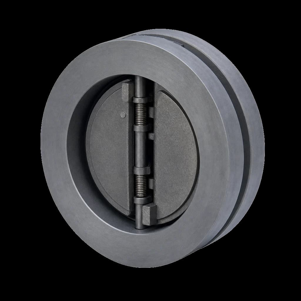
- A check valve makes a worse boundary still. Disc and hinge pin are sized for line differential, not 1.5x, and a dual-plate valve's torsion springs will not admit to being overloaded until the plates stop closing cleanly.
Valve position during hydrotest and flushing
The default is simple and almost never followed: every valve in the test section is fully open. Fully open means the seats see no differential, the body cavity fills and vents, and the closure member sits clear of the bore. A half-open valve is the worst case: the seat sits in the stream, flow accelerates past it, and every fragment of weld slag, grit and mill scale is fired across the sealing face.
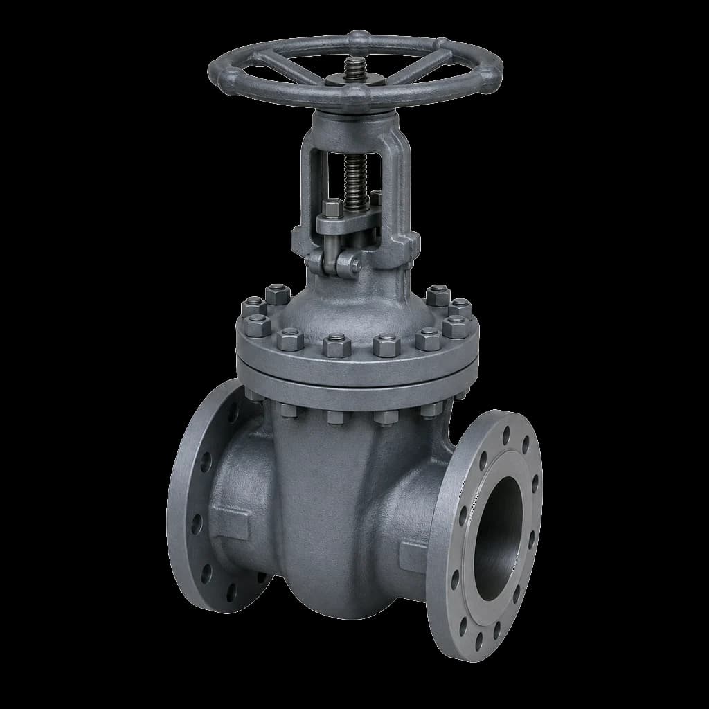
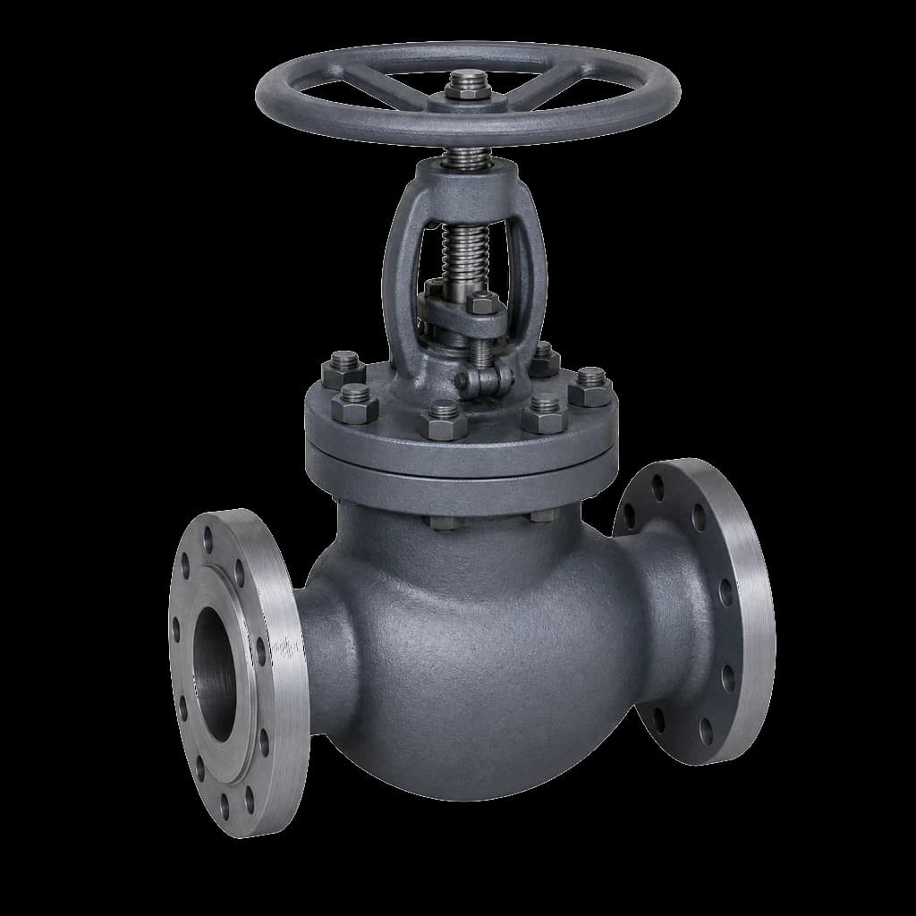
Do not throttle a gate valve. Not during flushing, not to balance a loop, not for five minutes. A wedge parked off its seat vibrates, and the wire-drawing damage it takes across the seat face is permanent — no amount of hard closing afterwards restores tightness. If flushing needs a controlled restriction, use a globe valve, designed to sit part-open, or a temporary orifice plate you can throw away.
Three positional details that cost money:
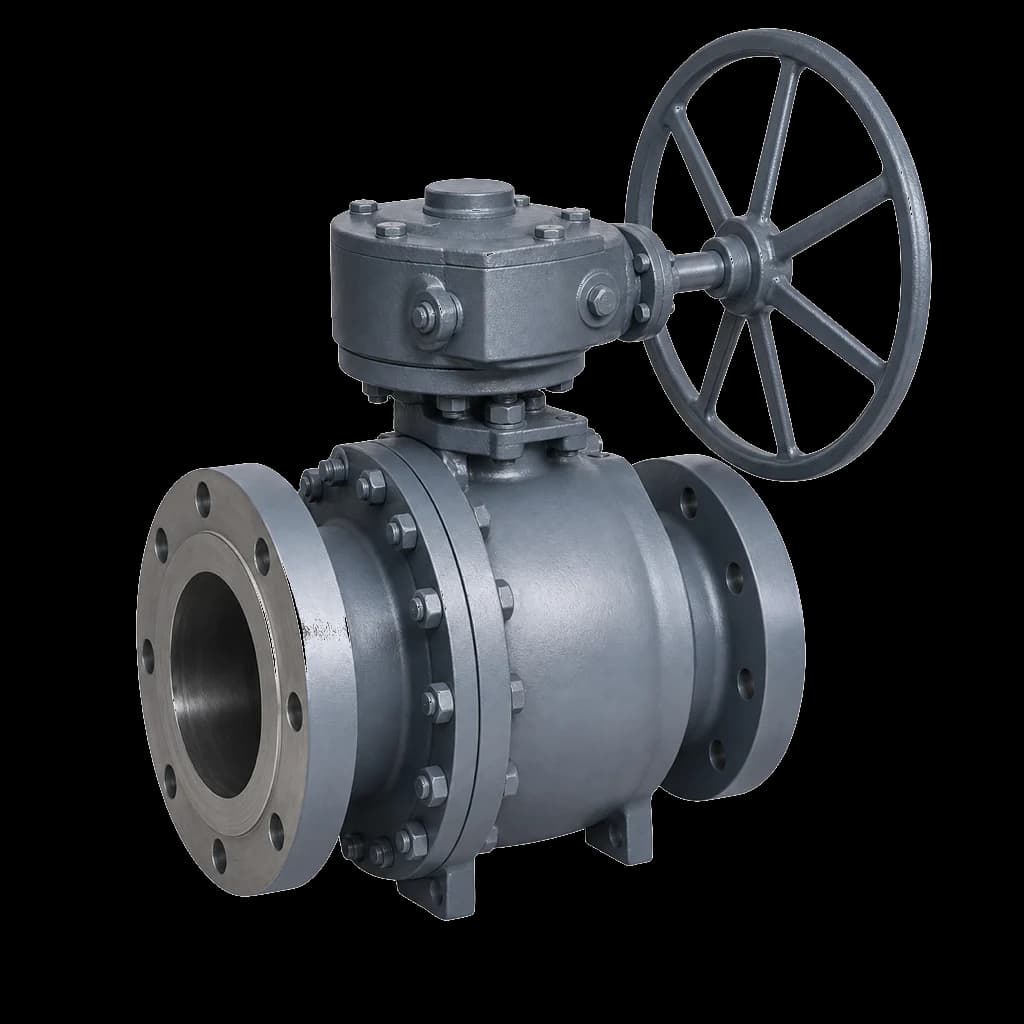
- Ball valves fill their body cavity. Test water sits there after the line is drained, and freezes, corrodes or turns biological. Cycle the valve once at low pressure after draining and use the cavity drain or vent if the valve has one.
- Wafer butterfly valves need their mating flanges fitted before the disc is opened. Open a wafer valve hanging free and the disc swings outside the body face, where the next bolt-up shears its edge.
- Double block and bleed is not a licence to test through one seat. Where the spec makes the valve the test isolation, the bleed must be open and monitored; otherwise pressure trapped between the seats loads them the wrong way.
Flushing, slag and temporary strainers
Flushing is where construction debris goes hunting for a soft target: seat faces, pump internals, control valve trim, instrument tappings. Protect them mechanically rather than hopefully.
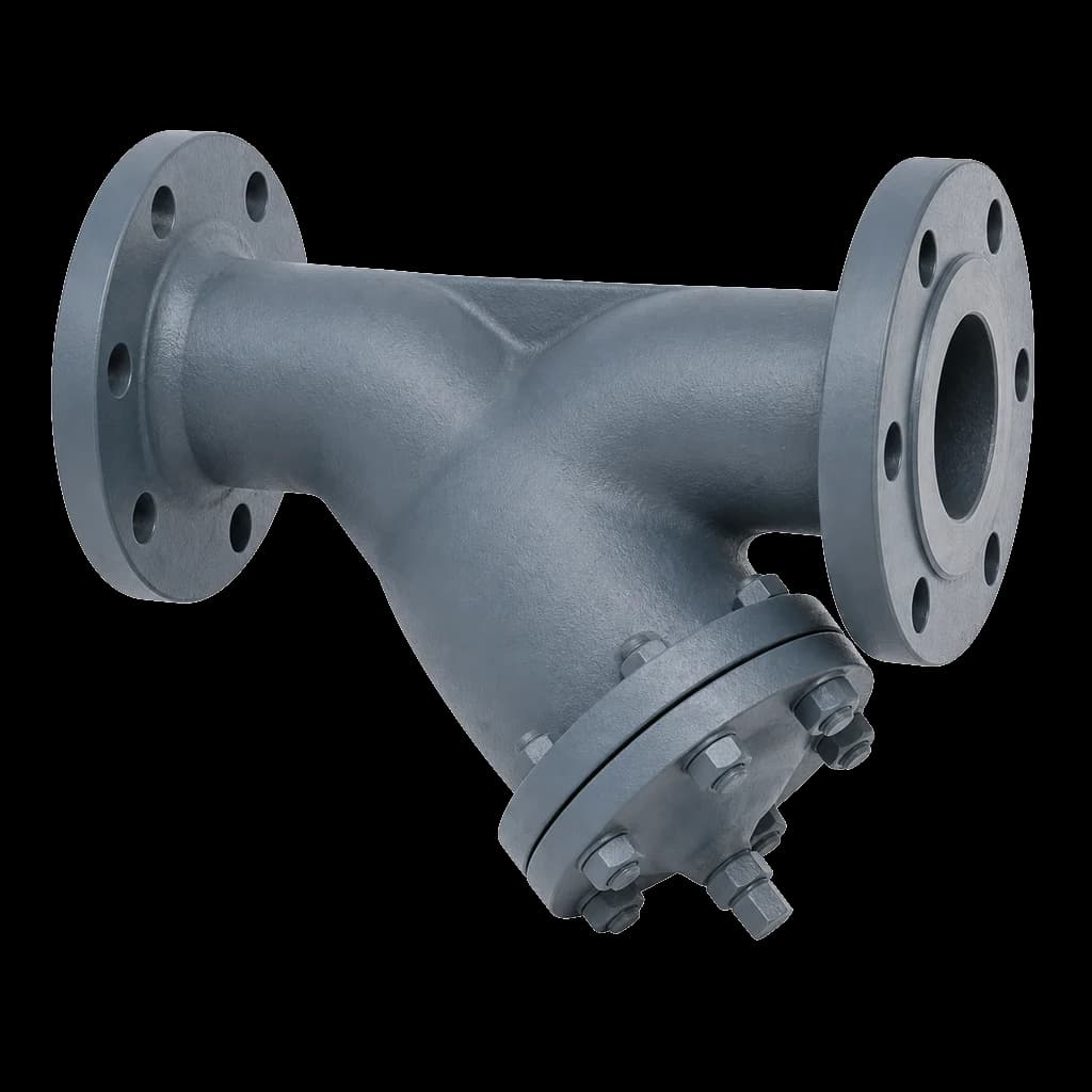
Fit a temporary conical start-up strainer — the witch-hat type, wire mesh backed by perforated plate so the mesh cannot collapse — at every pump suction and upstream of every control valve, and log the differential across it. A start-up strainer that has stopped fouling says the line is clean; one that has collapsed says it was undersized. Pick the mesh with the pump vendor, and size the permanent Y-strainers for service duty, not commissioning duty.
Where a line cannot be flushed clean around a valve, take the valve out. Replace check valves with spools for the flushing pass — a swing check disc chattering in a debris-laden stream loses its seat ring, and a dual-plate check valve loses spring tension long before anyone notices. Steam lines are blown, not flushed, and the velocity that cleans a superheater will strip a strainer screen and drive scale into globe valve trim: isolate and bypass instead.
Test water, chlorides and draining
Water quality is the failure mode nobody photographs. Austenitic stainless piping and CF8M bodies are vulnerable to chloride stress corrosion cracking, so client specs typically cap chloride in the test water at 30 to 50 ppm and require prompt draining and drying. Confirm the figure before the contractor draws from a borewell, and file the analysis in the test pack.
- Vent every high point while filling. Trapped air stores energy, and a pocket behind a closed valve turns a hydrostatic test into a pneumatic one.
- Watch metal temperature, not ambient. Pressurising thick carbon-steel bodies at dawn in a north Indian winter moves you toward the brittle end of the material's behaviour; warm the section or test later in the day.
- Use a calibrated gauge with the test pressure well inside its scale and attach the certificate. A gauge reading near full scale is the first thing a third-party inspector rejects.
- Drain low points fully and blow the line dry. Standing test water in a valve cavity does more damage over six idle months than the test did in ten minutes.
Site storage and valve preservation before commissioning
On Indian EPC and PSU projects, valves routinely arrive a year or more before the line is commissioned, ordered against a schedule that later slipped. Valve storage and preservation across that gap is an engineering activity with a register and a named owner, not a tarpaulin.
Keep end protectors on until the joint is made up — caps on threaded and socket-weld ends, plywood covers on flange faces, bevel protectors on butt-weld ends. Store off the ground on sleepers, under a roof, flange faces vertical where practical so water cannot pond on them. Grease machined faces and exposed stems, and never paint over the nameplate: an unidentifiable valve is unusable at joint inspection.
| Valve type | Storage position | Reason | What to inspect before installing |
|---|---|---|---|
| Wedge and slab gate | Fully closed | Seat faces shielded from grit | Water in the body cavity; stem thread condition |
| Globe | Closed, light seating force only | Protects disc and seat ring | Packing dried out; a stem taking a set |
| Floating and trunnion ball | Fully open | Ball surface protected between the seats | Cavity moisture; soft seats that have taken a set |
| Resilient-seated butterfly | Disc a few degrees open, inside the body face | Disc off the liner but not projecting | Disc bonded to the liner; edge damage from handling |
| Swing and dual-plate check | Restrained, end caps fitted | Stops the disc or plates flapping in transit | Bent stops, weak springs, hinge pin free movement |
| Y-type strainer | Screen fitted, cover bolted, blow-off plugged | Prevents the mesh being crushed | Mesh distortion; a screen quietly missing altogether |
Beyond about six months, exercise the valves: stroke each through full travel and return it to the storage position, re-grease gear operators, check breather plugs, keep electric actuators heated or dry-stored. Record it. On PSU and EPC contracts the preservation register is contractual, and its absence is the first thing an inspector uses to reject a warranty claim — a theme of our valve procurement mistakes guide.
Hydrostatic test certificate and report format
Keep the two documents apart: clients and TPI agencies audit them separately. The valve's hydro test certificate comes from the manufacturer, references API 598, and is traceable to the heat number on the EN 10204 3.1 or 3.2 MTC; for IBR steam service it travels with Form III-C. The system hydrostatic test report is raised on site against a line or test package number.
A hydrostatic test report format that survives audit records the line or package number, the P&ID reference, test medium and its chloride analysis, design pressure, calculated and applied test pressure, hold duration, start and end gauge readings, metal temperature, gauge serial number with calibration due date, a marked-up isometric showing blinds and isolations, and signatures from contractor, client and inspector. For the incoming-material half of that dossier, see the valve inspection and FAT checklist.
Specifying valves that survive commissioning
Some of this is procurement, not construction. Where a line will be dirty at start-up, specify metal-seated or hard-faced trim instead of soft seats and accept the higher cost — a stellited seat face on a cast steel gate valve tolerates debris that would destroy an RPTFE seat. Order the temporary start-up strainers alongside the permanent ones. Write storage and preservation into the purchase order, so end caps, preservation coating and an instruction sheet arrive with the valves.