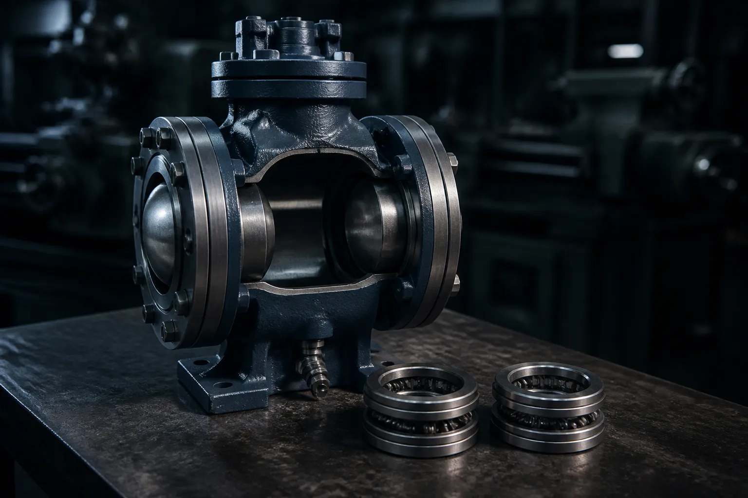
A double block and bleed valve is the most confidently specified and least accurately understood line item on an Indian hydrocarbon tender. Specifications write DBB when they mean two independent barriers, write DIB when they mean DBB, and say nothing about the liquid trapped in the body cavity. API 6D defines both terms precisely, they are not interchangeable, and one carries a note saying it does not give you double isolation.
What a double block and bleed valve actually does
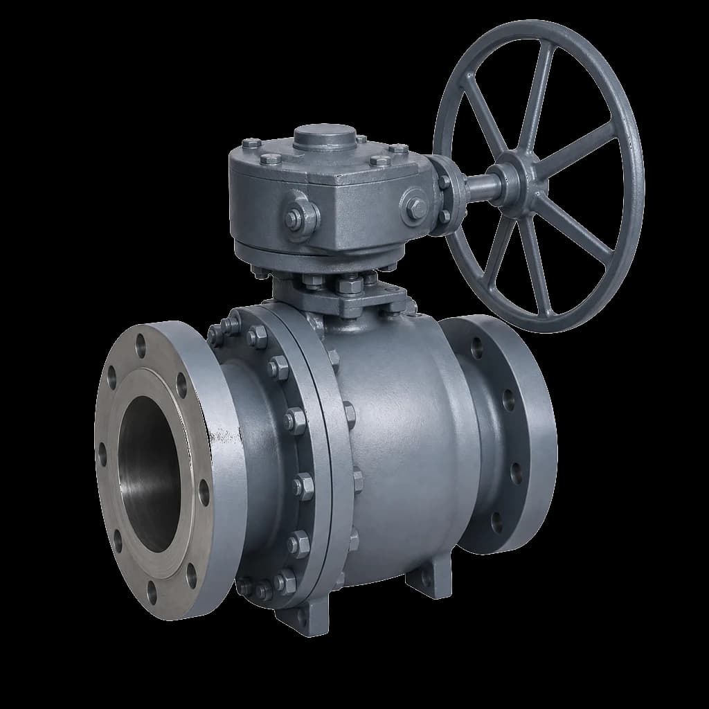
A trunnion-mounted ball valve carries two seat rings, one either side of the ball, each in a spring-loaded pocket. Close the valve and the volume between them — the body cavity — is shut off from both sides of the line. Tap that cavity, fit a small bleed valve, and you can crack the bleed with the valve closed. Nothing coming out means the seat facing the live side is holding: isolation you can prove rather than assume.
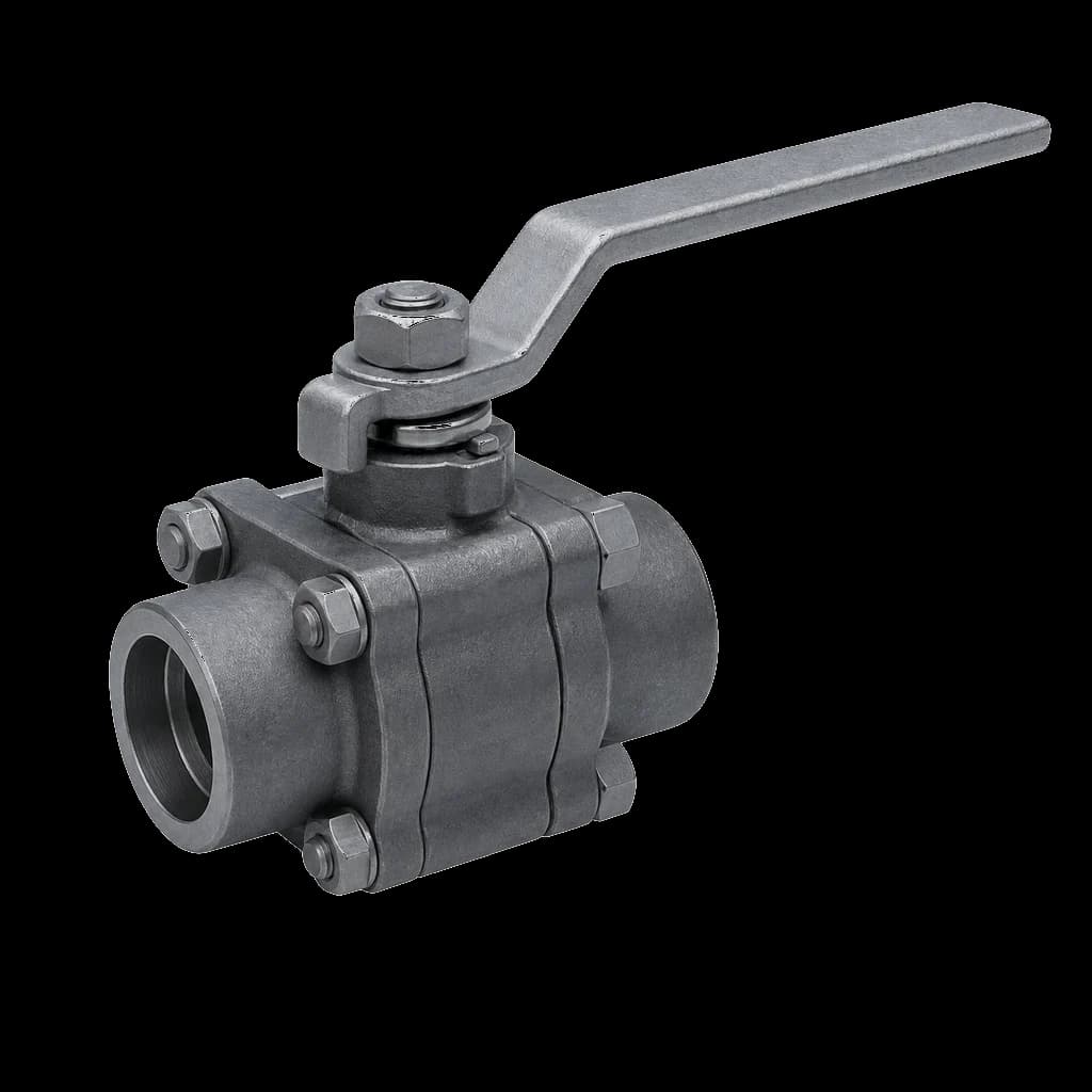
Among ball valves, only a trunnion design does this. In a floating ball valve, line pressure pushes the ball onto one seat: a single energised seal, and no cavity bounded by two of them — the difference between floating and trunnion construction is what makes double block possible. Through-conduit slab and expanding gate valves reach it by other geometry, but on most Indian enquiries the trunnion ball valve is the practical route.
DBB vs DIB: what API 6D actually says
API 6D defines a double block and bleed (DBB) valve as a single valve with two seating surfaces that, closed, seal against pressure from both ends, with a means of venting the cavity between them. "Both ends" means bidirectional: the valve blocks whichever end is live. It does not mean two barriers against one live end, and the standard says so in a note — the configuration does not provide positive double isolation when only one side is under pressure.
Seat mechanics explain why. Where both seats are self-relieving, the seat facing the live line is pressed onto the ball and seals; if it passes, cavity pressure rises and the far seat — built to lift the moment cavity pressure exceeds line pressure — vents the leakage onward into the line. One working barrier and a relief path, not two.
A double isolation and bleed (DIB) valve is defined differently: two seating surfaces, each of which, closed, seals against pressure from a single source, with a means of venting the cavity. Each seat holds on its own account, which it can do only because it is built to seal against cavity pressure as well as line pressure.
DIB-1 and DIB-2
Practice splits DIB in two, and both appear on EIL and GAIL datasheets. DIB-1 uses double-piston-effect seats on both sides: two barriers in either direction. DIB-2 pairs one double-piston-effect seat with one self-relieving seat: two barriers from one direction only. DIB-2 costs less and is correct where the hazardous side is fixed — a pig trap, a blowdown tie-in — and worthless the moment the direction arrow is ignored during erection.
| Configuration | Seat design | Isolation delivered | Cavity relief |
|---|---|---|---|
| DBB | Both seats single-piston-effect | Blocks whichever end is live; no guaranteed second barrier | Automatic, past a seat into the line |
| DIB-1 | Double-piston-effect both sides | Two barriers, either direction | None inherent — external relief or piped vent |
| DIB-2 | One double-piston-effect, one self-relieving | Two barriers from the marked side only | Automatic, through the self-relieving seat |
Self-relieving vs double-piston-effect seats
It comes down to seat geometry. A seat ring sits in its pocket, pushed at the ball by springs and by whatever pressure reaches its exposed annular areas — and which areas it reaches decides whether it loads the seat or lifts it.
- Single-piston-effect (SPE), or self-relieving: line pressure loads the seat onto the ball, cavity pressure lifts it off. It seals one way and doubles as the cavity relief device — which is why a stock trunnion valve is DBB, not DIB.
- Double-piston-effect (DPE): the areas are arranged so both line and cavity pressure load the seat onto the ball. It seals bidirectionally — the basis of true double isolation — and cavity pressure has no route past it, so every DPE seat creates a relief problem to solve.
- Seat insert sets temperature and cycle limits, not the piston effect. RPTFE, nylon, PEEK and metal seats come in both forms, so give insert and piston effect separate datasheet rows.
Seat pockets differ from maker to maker, and the pressure at which a self-relieving seat lifts varies with spring rate and area ratio. API 6D limits how far cavity pressure may rise above the rated pressure before the seat relieves, and defines a cavity relief test to prove it — put that test in the inspection and test plan.
Body cavity overpressure: the failure mode nobody budgets for
Close a trunnion valve on a liquid line and a fixed volume is trapped in a nearly rigid steel cavity. Liquids expand with temperature and barely compress, so heat has nowhere to go but into pressure — of the order of a few bar per degree Celsius for water, steeper for LPG and condensate. Real cavities flex a little, so measured rises are lower; but water left in the cavity after hydrotest, or an aboveground valve warmed by the sun, can carry it past the rated pressure of a Class 300 body.
What fails is rarely the casting. It is the seat insert, the seat carrier, the stem seal or the body-to-adapter joint — the valve starts passing, weeps at the stem, or the gearbox will not turn. Cavity relief is the buyer's decision, not the valve maker's.
- Self-relieving seat. The default on a stock trunnion valve — and the option you throw away the moment you write DIB-1.
- External cavity relief valve. Piped from the body vent back to the upstream side; standard on DIB-1 and the only defensible answer when both seats are DPE. It is a separate item with its own set pressure and certificates — put it in the enquiry.
- Piped vent to a closed drain or flare. Where relieving into the process line is unacceptable: custody transfer, product segregation, sour or toxic duty. Agree tubing, fittings and bracket scope before the order.
- Cavity vent hole drilled through the upstream seat or ball. Permanent, and it makes the valve unidirectional. Never accept it on a valve you specified as bidirectional.
One valve, or a double block and bleed valve arrangement
A specification calling for a "double block and bleed valve arrangement" at a battery limit often does not mean one valve: it means two valves in series with a bleed on the spool between them — two bodies, two stems, two independent seat sets, and no argument about piston effects. It costs length, welds and supports — every joint a leak path — but it buys independence: overhaul one barrier without breaking containment on the other.
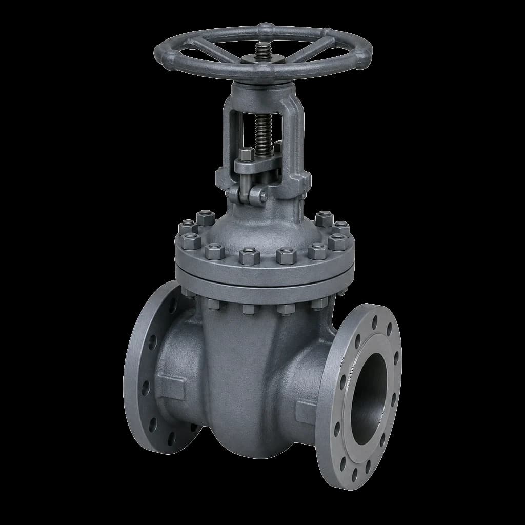
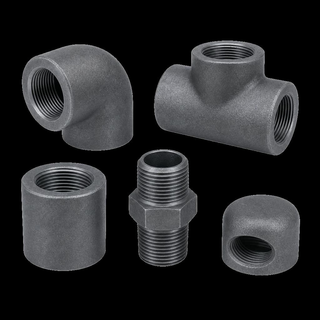
At refinery and terminal unit boundaries it is still standard, often built from ordinary cast steel gate valves with a socket-weld bleed boss on the spool — which is why the small-bore fittings and the bleed valve belong in the same enquiry as the block valves.
The DBB symbol, and what tender documents get wrong
Some P&IDs draw two valve symbols with a bleed between them where one integral valve is intended; others hang a "DBB" note off a single body. No convention is universal and ISA 5.1 does not settle it, so treat the symbol as a reminder — the requirement lives on the datasheet.
- Write the configuration in words: DBB, DIB-1 or DIB-2, the piston effect seat by seat, the cavity relief method beside it, and — where the valve is unidirectional — the isolating direction, arrow cast into the body rather than painted.
- Size and type the bleed. A 1/2" NPT boss with a plug in it is not a bleed: specify the valve — a needle valve vents a live cavity under control — and say where it discharges.
- Do not write DBB when you mean positive isolation. No valve substitutes for a physical break: vessel entry and hot work under OISD-aligned permit regimes demand a spade or spectacle blind, and a DBB valve with a monitored bleed is a limited measure the plant's isolation standard must allow.
Where each configuration belongs
Every extra barrier adds a component that can fail. The right configuration follows the consequence of a leak-through, not the budget.
| Duty | Sensible configuration | Reasoning |
|---|---|---|
| Pipeline sectionalising, pig trap isolation | Trunnion DBB, or DIB-2 with the DPE seat facing the trap | Provable bleed both ways; the cavity must still relieve |
| Metering and prover skid isolation | DIB-1 with external cavity relief | Measurement is only as good as the isolation; both seats must hold |
| Instrument, gauge and sampling isolation | Monoflange or two-valve manifold with a needle bleed | Small bore, high pressure; a needle bleed vents the cavity under control |
| Water, air and low-hazard utility service | Do not specify DBB at all | Extra barriers buy nothing here; one valve and a drain is right |
Sectionalising valves, pig traps and metering skids drive most of the DBB and DIB enquiries reaching us from oil, gas and CGD projects, and nearly all land on trunnion API 6D valves. Settle the rest of the API 6D specification sequence alongside the isolation configuration: seat insert and piston effect constrain one another.
What the RFQ has to say
- Configuration in words — DBB, DIB-1 or DIB-2 — and the isolating direction where the valve is unidirectional.
- Piston effect seat by seat, insert material and its temperature limit, bore full or reduced, and whether the line is pigged.
- Cavity relief method: self-relieving seat, external relief valve with a stated set pressure, or piped vent — and who supplies it.
- Bleed connection size and end type, the bleed valve itself, and where it discharges.
- Fire-safe qualification, antistatic device, and emergency seat and stem sealant injection where the service warrants them.
- Testing and documentation: shell and seat tests to API 6D, seat testing in both directions wherever DIB is claimed, drift test for pigged lines, EN 10204 3.1 or 3.2 certificates, and third-party inspection where the tender demands it.