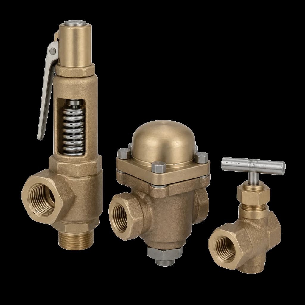
Three valves decide whether a boiler house runs quietly or eats maintenance hours: the boiler feed check valve at the drum inlet, the blowdown valves at the lowest point of the shell, and the main steam stop at the outlet. None is a commodity line item. Each sits inside the Indian Boiler Regulations, each carries its own certification, and each has a characteristic failure mode when it is bought as an ordinary globe or gate valve off the piping schedule.
The boiler-house valve schedule
IBR calls the valves bolted directly to the pressure part mountings. The boiler maker supplies some of them; the rest lands on the buyer's or the piping contractor's schedule, and that is where the specification goes thin.
- Safety valves — set and sealed under IBR by the boiler maker, not a bought-out line.
- Main steam stop valve on the drum or superheater outlet, plus a second stop where boilers share a header.
- Feed check valve — a screw-down non-return valve, one per independent feed line, with a stop valve between it and the boiler.
- Blowdown valves — intermittent from the lowest point of the shell or mud drum, plus a continuous surface-blowdown valve on the skimmer nozzle.
- Drains, vents and instrument isolation — small-bore forged globe and needle valves, inside IBR scope just as much as the 6" stop.
| Service | Valve type | Typical body | Trim |
|---|---|---|---|
| Main steam stop, saturated outlet | Angle or straight globe, screw-down | ASTM A216 WCB | 13% Cr, hardfaced seat |
| Superheater outlet stop | Globe or parallel slide gate | ASTM A217 WC6 / WC9 | Stellite 6 overlay |
| Second stop at a shared header | Gate or globe, free-blow drain between | Matched to the line | 13% Cr minimum |
| Feed check | Screw-down non-return, angle or straight | A105 forged, Class 800 | 13% Cr or 316, hardfaced |
| Bottom blowdown | Plug or Y-pattern, two in series | A216 WCB or A105 | Hardfaced seats |
| Continuous blowdown | Orifice or needle throttle plus isolator | ASTM A105 | Hardfaced or 316 |
Everything downstream of the main stop — mains, separators, traps, condensate return — follows different rules, set out in the steam service valves guide.
How a boiler feed check valve actually works
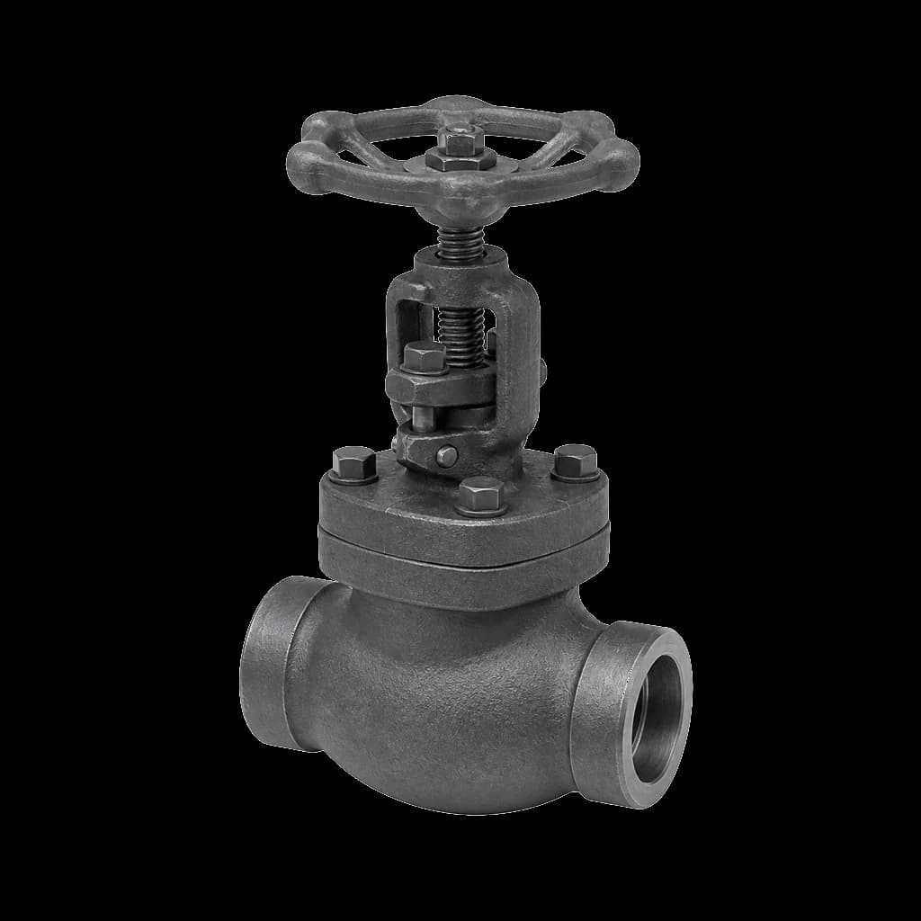
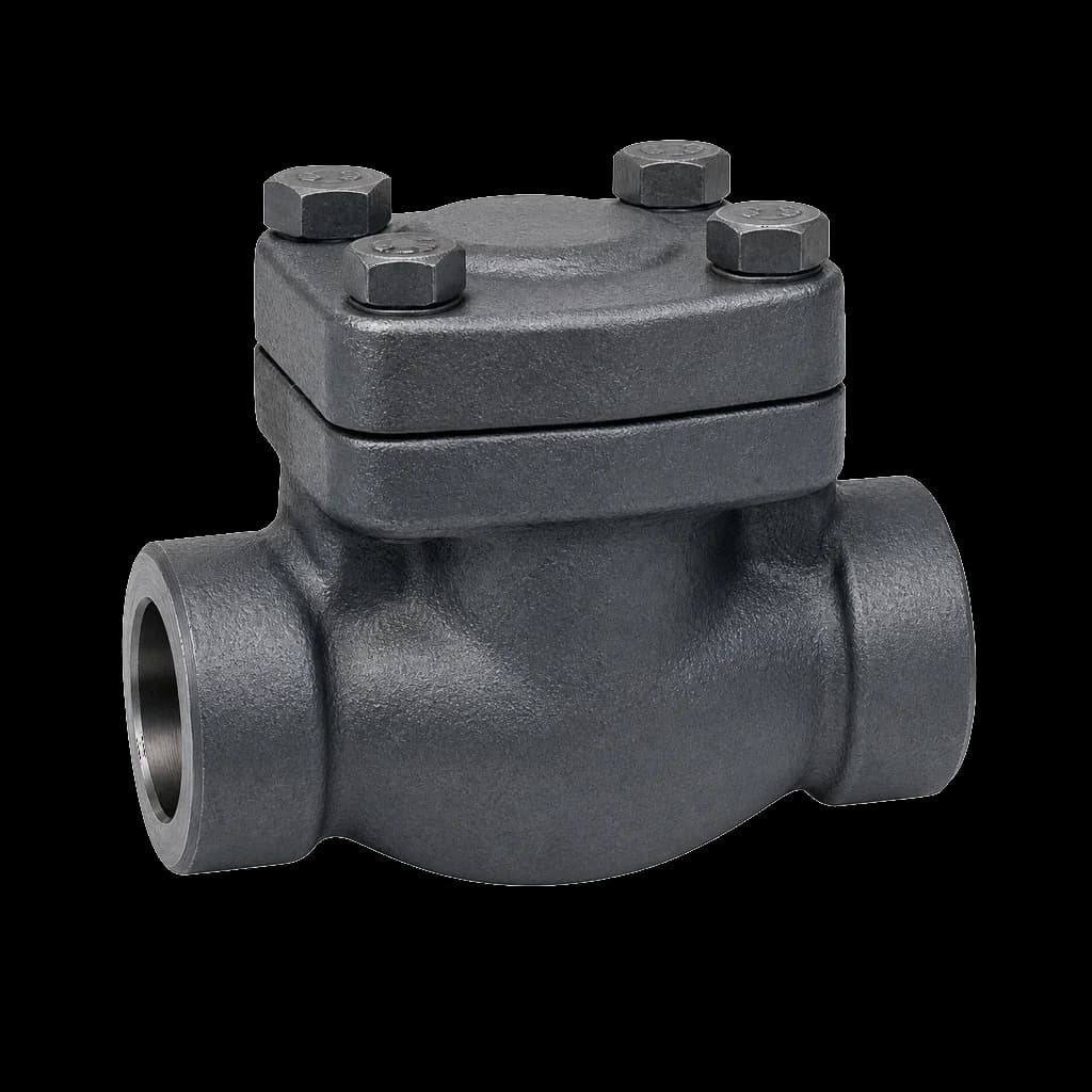
A feed check valve is a screw-down non-return valve. It has a globe or angle body, a disc free to lift off its seat, and a spindle bearing down on the disc without being attached to it. Back the handwheel off and the disc floats: feed water pushes it open and any reversal seats it. Screw the spindle down and you first limit the lift, then close the valve positively. One body, two duties.
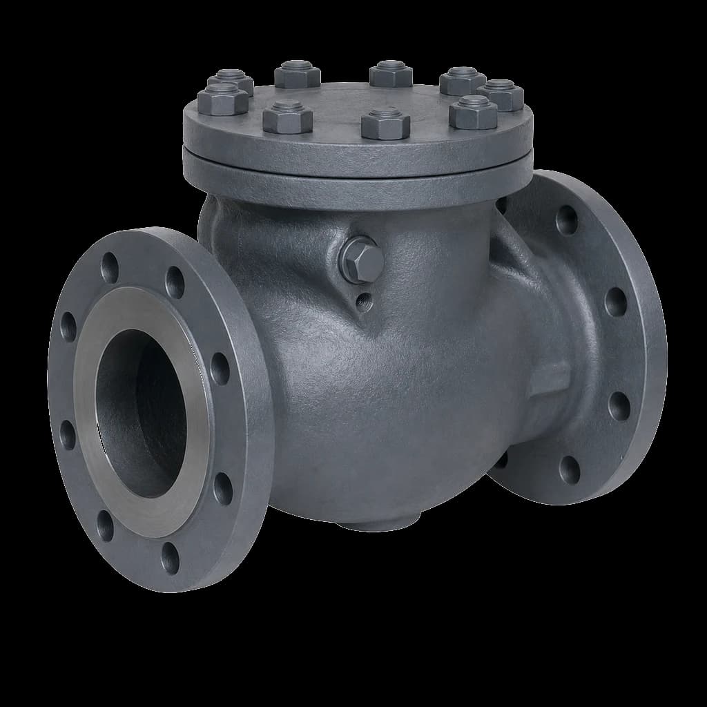
That second duty is the point: a plain swing check cannot be shut, so it cannot isolate the drum from the feed line. Our check valve types guide sets out where swing, dual-plate and wafer discs belong elsewhere; on the boiler, IBR and the mounting drawing expect the screw-down non-return.
Order matters. ASME Section I puts the check valve near the boiler with a stop valve between the check and the boiler, and IBR mounting drawings follow the same reasoning: shut that stop and the check can be stripped with the boiler still live. From the pump the run is feed control station, feed check, feed stop, drum. Where a screw-down non-return bolts straight onto a shell boiler, it is its own isolation. Two independent feed lines mean two checks and two stops.
Do not take the class from drum pressure. The boiler external piping rules in ASME B31.1 require a margin over boiler MAWP on the feed line, and the line also sees pump shut-off head. A small-bore feed check on a 17.5 kg/cm² boiler is therefore normally forged Class 800, not the Class 300 the drum figure alone would suggest. State the pump shut-off head on the enquiry and let the class follow from it.
Trim is 13% Cr (ASTM A182 F6a) as the floor, hardfaced where the boiler cycles. The classic failure is a wire-drawn seat: the operator throttles at the check instead of the feed regulator, the seat erodes, and the valve passes on shutdown while drum level creeps.
Main steam stop valve and the second stop
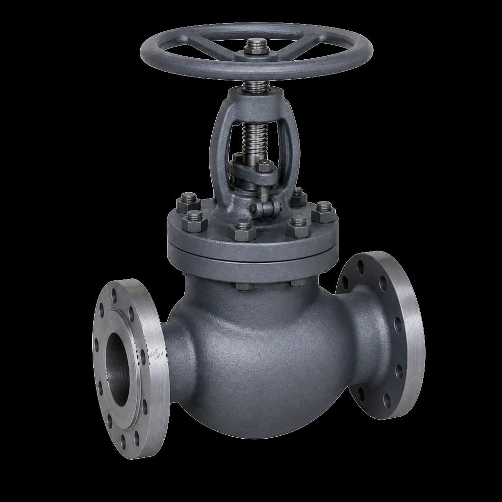
On shell and small water-tube boilers the main steam stop is a right-angle screw-down globe bolted onto the drum or superheater outlet. On larger units a parallel slide gate takes over: a wedge closed cold and then heated can lock into the seat, while parallel slide discs stay free through the thermal cycle.
Where two or more boilers discharge into a common header, ASME Section I and IBR practice alike require two stop valves in series with an ample free-blowing drain between them. That drain is not a formality: it is how an operator proves a shut boiler is isolated before anyone opens a manhole. A tender showing one stop valve per boiler on a shared header has missed something the inspector will not.
The main stop is an isolating valve, never a control valve. Every hour it spends part-open wire-draws the seat you will later need for a tight shut-off; steam-side control belongs to the governor or a pressure-reducing station.
Blowdown valves: intermittent and continuous
Bottom blowdown
Bottom blowdown is a short, violent duty: the valve opens onto full drum pressure, the water flashes across the seat and carries sludge with it. An ordinary wedge gate valve is the wrong choice — solids settle in the seat pocket below the wedge so it no longer lands home, and the two-phase flow cuts the seating faces. Use a purpose-built blowdown valve — angle-pattern plug or ram type, or a straight-through Y-pattern — hardfaced throughout.
Above roughly 7 kg/cm² (100 psi) both ASME Section I and IBR expect two blowdown valves in series, and the operating sequence is what makes them last: open the inner valve fully first, blow with the outer, close the outer first and the inner last. The outer absorbs the erosion; the inner is barely throttled and stays the tight seal. Reverse it and you destroy the valve you cannot replace on line.
Continuous surface blowdown
Continuous blowdown draws from a skimmer nozzle just below working water level to hold boiler-water TDS inside the maker's limit. It is a throttling duty — an orifice or needle-type element, hardfaced or stainless, with an isolating valve upstream so it can be re-trimmed on line. Route the discharge to a blowdown vessel, never an open drain.
Body materials: where WCB stops and WC6 starts
Body material follows the metal temperature at that valve, not the boiler's headline rating. Saturated steam off a drum at 17.5 kg/cm² is around 210 °C and carbon steel is comfortable. A superheater outlet at 480 °C is a different metallurgy problem.
| Metal temperature | Cast body | Forged body | Where it shows up |
|---|---|---|---|
| Up to about 425 °C | ASTM A216 WCB | ASTM A105 | Feed lines, drum outlet, blowdown |
| About 425–540 °C | ASTM A217 WC6 (1.25Cr–0.5Mo) | ASTM A182 F11 | Superheater outlet, captive power |
| About 540–590 °C | ASTM A217 WC9 (2.25Cr–1Mo) | ASTM A182 F22 | High-temperature main steam, reheat |
| Above 590 °C | ASTM A217 C12A (9Cr–1Mo–V) | ASTM A182 F91 | Utility-class headers |
The 425 °C line is not arbitrary: carbon steel held above it for long periods can graphitize, and its allowable stress is falling away in any case, while chrome-moly grades hold creep strength. On the water side the enemy is flow-accelerated corrosion, which thins plain carbon steel in low-oxygen feed water and bites hardest downstream of a throttling element — an argument for chrome-bearing material at every throttling point. Captive boilers in the paper and sugar plants we supply sit in the first two rows.
Trim, gland packing and bolting
Specify trim by composition, not by a trim number alone: 13% Cr stem and disc as the baseline, Stellite 6 overlay on the seating faces of the main stop and both blowdown valves, 316 where feed chemistry argues for it. Trim numbering differs between makers, so state the composition and cross-check it against the maker's table — our valve trim materials guide sets out the combinations.
PTFE gland packing has no place at boiler temperatures. Use die-formed flexible graphite rings with braided carbon end rings, live-loaded on valves that cycle daily. Bonnets are bolted through Class 600 and pressure-seal from Class 900 up. Spiral-wound 316/graphite gaskets suit the flanged joints, and A193 B7 studs with A194 2H nuts serve to about 400 °C, above which chrome-moly grades such as A193 B16 take over.
IBR scope and Form III-C
IBR treats a pipe as a steam pipe once the steam pressure in it exceeds 3.5 kg/cm² gauge, or once its internal diameter exceeds 254 mm at more than 1 kg/cm² gauge; fittings and mountings on such a pipe fall under the same regulations. Feed lines enter separately — a feed pipe is any pipe under pressure carrying feed water directly to the boiler, whatever its bore. Most Indian boiler houses therefore sit inside IBR scope from the drum outward.
Form III-C follows an IBR valve or fitting: the inspecting authority — a state Boiler Directorate or an authorised third party — issues it against approved drawings, approved materials and a witnessed hydrostatic test. An EN 10204 3.1 mill certificate is no substitute: the MTC certifies material, Form III-C certifies the item under the regulations, and an IBR line needs both. Settle it at enquiry stage: a valve made outside the IBR route cannot usually be certified afterwards, and the replacement lands on your shutdown critical path.
Specifying the schedule so it does not come back
An enquiry carrying these lines against every item gets a quotable, buildable, certifiable offer. One carrying only size and class gets a guess.
- Boiler MAWP, design temperature and the actual metal temperature at that valve.
- Whether the item is inside IBR scope and needs Form III-C against that line.
- Pattern and orientation — angle or straight, and which way flow turns into the nozzle.
- Ends: flanged RF to ASME B16.5, butt weld to B16.25 with the mating schedule, or socket weld to B16.11.
- Feed check: line design pressure including pump shut-off head, not drum pressure.
- Blowdown: valves in series, hardfacing extent, discharge routing.
- Documents: EN 10204 3.1 or 3.2 MTCs, Form III-C, witnessed hydro report, GA drawing.