The compressed air pipe is the last thing designed and the first thing blamed. A plant buys a good compressor, a dryer and a correctly sized receiver, then runs the distribution in whatever galvanised pipe was on site, tees off the bottom of the header, and pays for the pressure drop for fifteen years. Compressed air is the most expensive utility in a factory, and the piping is where much of it is lost. This guide covers sizing, materials, joints, drain legs and isolation valves.
Compressed air pipe sizing starts with pressure drop
The compressor discharges at a set pressure — commonly 7 to 8 bar g for general plant air. Every point of use has a minimum pressure below which its tool or cylinder stops working. The only variable in between is the loss in the pipe, which is yours to control. Good practice holds the total drop from receiver to furthest point of use under about 0.3 bar, no more than a third of it in the main header. Those are design targets, not code limits.
The reason to be strict is economic. When the line loses pressure the field fix is to wind the compressor up a bar, which costs roughly 7 percent more shaft power, permanently, and pushes more air through every leak and blow gun. An undersized header is paid for twice: in lost pressure, and again in artificial demand.
Velocity limits that keep the drop honest
Velocity is a proxy for drop, not a substitute for calculating it, but it is a fast first cut. Conventional practice keeps main headers at or below about 6 m/s and allows branches and drop legs up to roughly 15 m/s because they are short. Push past that and both drop and condensate carry-over rise steeply.
| Nominal bore | Approx. bore, medium class (mm) | Free air at 6 m/s (m³/min) | Free air at 6 m/s (cfm) |
|---|---|---|---|
| 25 NB | 27.3 | ~1.7 | ~60 |
| 40 NB | 41.9 | ~4.0 | ~140 |
| 50 NB | 53.1 | ~6.4 | ~225 |
| 65 NB | 68.9 | ~10.7 | ~380 |
| 80 NB | 80.9 | ~14.8 | ~520 |
| 100 NB | 105.3 | ~25 | ~890 |
| 150 NB | 155.4 | ~55 | ~1930 |
Those capacities follow from bore and velocity at a compression ratio of about 8:1, so they scale with working pressure: the same pipe carries more free air at 10 bar g and less at 4 bar g. With a candidate size in hand, work the drop over the equivalent length, not the tape-measure length — screwed elbows, tees and valves add heavily to it, so use the figures published for the fittings you buy.
Ring mains, dead-end spurs and sectionalising
Layout buys more than pipe size does. A ring main fed from the receiver splits the flow into two paths, so the effective length for a given demand is roughly halved and the drop falls with it, for the price of some extra pipe and a few more valves. Dead-end spurs are where drop accumulates and condensate collects.
Run a ring rather than a tree wherever the building allows, sectionalise it with full-bore ball valves so a leaking spur can be isolated without stopping the plant, and size any dead-end spur one bore up where peak draw is high — blow-off stations, pneumatic clamping, PET blowing and bag houses all pull far more than their average suggests. Oversizing the header now is cheap; re-piping a running plant is not.
Compressed air pipe materials: GI, seamless, stainless and aluminium
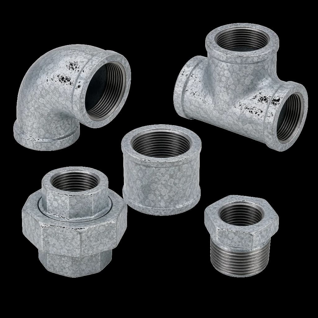
The Indian default is galvanised steel to IS 1239 (Part 1), medium or heavy class: cheap, available everywhere, threaded on site, familiar to every fitter. Its weaknesses are the threads, each a candidate leak path, and the zinc — a chronically wet line sheds scale and flakes into valves, cylinders and solenoids. Behind a maintained dryer that is manageable; on saturated air it is not.
| Material | Where it fits | What to watch |
|---|---|---|
| GI to IS 1239 (Part 1), medium or heavy class | Screwed plant air; most Indian factories | Thread leaks; zinc scale in wet lines; site-cut threads need touch-up |
| Seamless carbon steel, ASTM A106 Gr B | Welded mains; hot line before the aftercooler | Internal rust in wet air; welder qualification and NDT |
| Stainless, ASTM A312 TP304 or TP316 | Instrument air; food, pharma, coastal and oil-free plants | Cost; match fittings and valve trim to the pipe |
| Extruded aluminium modular systems | Clean, fast-install mains and drops | Proprietary fittings lock you to one range |
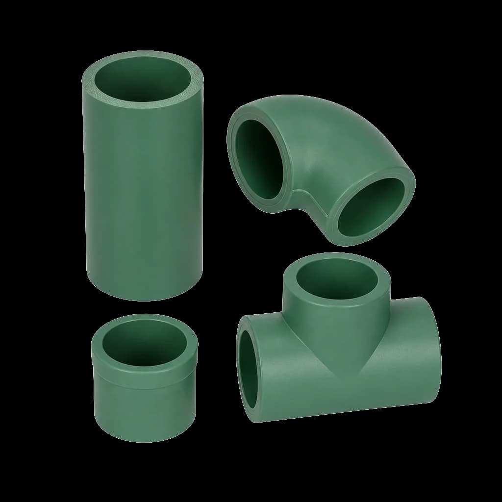
| PVC, uPVC or CPVC | Never on compressed air | Shatters under stored energy; attacked by compressor lube oil |
If it is GI, get the class right. IS 1239 (Part 1) grades tube light, medium and heavy — yellow, blue and red colour bands — with galvanising to IS 4736, and light class has no business on an air header. Fittings fall under IS 1239 (Part 2) for steel screwed fittings and IS 1879 for malleable cast iron; name one in the BOQ. Our guide to IS 1239 pipes and fittings unpacks classes, tolerances and marking.
One rule is absolute: never run compressed air in PVC or CPVC. A liquid line that fails splits and drips; a gas line at 7 bar stores real energy, and rigid thermoplastic fails by shattering into fragments. Compressor lube oil aerosol attacks the plastic and accelerates that failure. PVC makers exclude compressed gas from their published scope of use, and compressor manuals say the same. If a non-metallic run is unavoidable, use a system its maker certifies for compressed air, and follow those instructions exactly.
Fittings and joints: threaded, grooved or welded
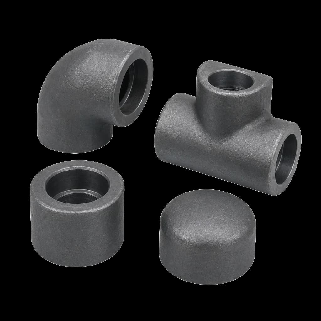
Threaded is the default up to about 50 NB: cheap, demountable, no hot work permit, built from standard GI threaded fittings any contractor can install. The cost is leak count, since every thread eventually weeps. Grooved couplings go in fast and come apart again — good for retrofits in running plants, provided the groove is rolled properly and the gasket suits oil-bearing air. Welding gives the lowest leak count and the cleanest bore on large mains and stainless instrument air, at the price of qualification and radiography. Full comparison: grooved vs threaded vs welded piping.
Whichever you pick, state the thread standard. Mixed NPT and BSP on one site is the commonest cause of leaking drops: the 60-degree and 55-degree forms start on each other and then refuse to seal.
Isolation valves on an air header
Air is compressible, low viscosity, near ambient and carries a little oil and water. That combination is unforgiving: almost any valve passes a hydro test on water, and almost none holds air once the seat is scratched or the gland is tired. Specify full-bore quarter-turn ball valves wherever size and budget allow.
| Location | Specify | Why |
|---|---|---|
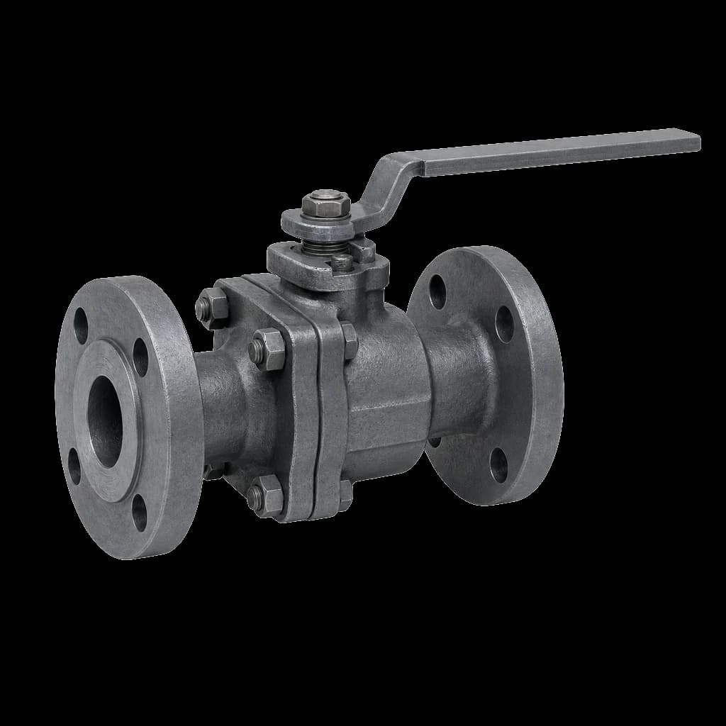
| Receiver outlet, main header isolation | Full-bore ball valve, Class 150 or PN 16, PTFE or RPTFE seat | Near-zero drop when open, tight shut-off, quarter turn |
| Ring main sectionalising | Full-bore ball valve, lockable lever | Isolates one shop or one leg without dropping the ring |
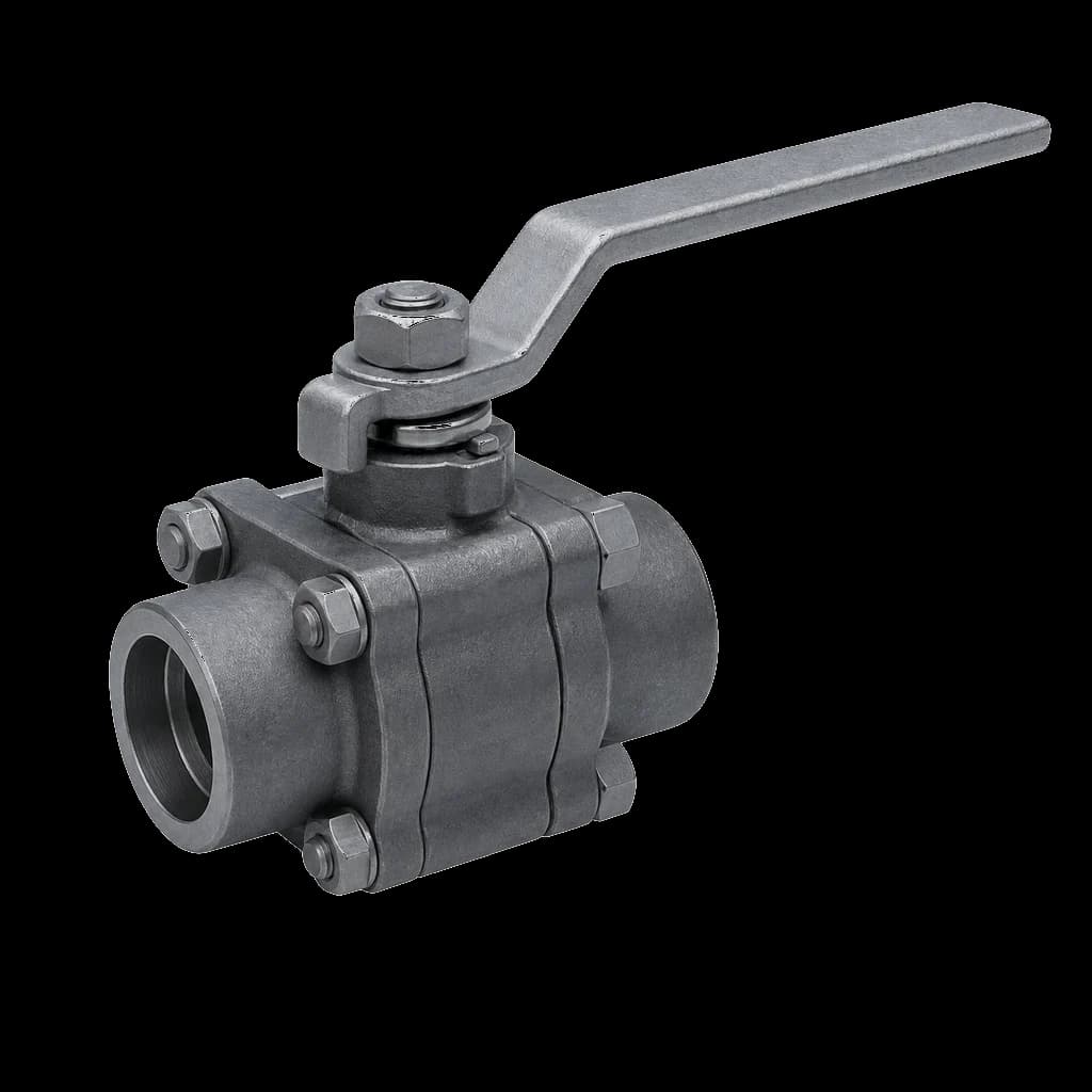
| Machine drops, 15-50 NB | Forged-body screwed-end ball valve | Compact; takes a lockout device for maintenance |
| Large mains, 200 NB and above | Gear-operated resilient-seated butterfly valve, nitrile seat on oil-carrying air | Ball valve cost and weight dominate at that size, and open-disc drop is acceptable on a main |
| Dryer, filter and receiver bypass | Three-valve bypass in ball valves | Service the dryer without shutting the plant or running it wet |
- Never throttle a gate valve on air. A part-open wedge chatters and wears the seat for no useful control; regulation is a regulator's job — gate vs globe vs ball valves.
- Default to full bore on headers and on drops feeding high-peak machines; reduced bore costs pressure at the point you were protecting — full bore vs reduced bore ball valves.
- Check the seat against real temperature. PTFE and RPTFE suit after-cooled plant air; upstream of the aftercooler, check the rating against the discharge temperature.
- Vent downstream of every machine isolation valve so the fitter can prove zero pressure before breaking a joint, and lock the lever of anything isolating a machine. A tag is not a lock.
Condensate, drain legs and takeoff geometry
A refrigerated dryer typically holds a pressure dew point near +3 °C — ISO 8573-1 humidity class 4 — dry enough for most plant air until part of the line runs colder than that. A rooftop header in a north Indian December condenses water inside itself, however good the dryer is. Lay the run out so condensate ends where you want it.
- Slope the header roughly 1 in 100 in the flow direction, and end every sloped run at a drain leg.
- A drain leg is a full-bore vertical extension of the main, down to an isolation valve and an automatic drain. A 15 NB stub under a 100 NB header collects nothing.
- Take every branch off the top of the header, gooseneck over and down. Condensate cannot climb, so a top takeoff keeps water out of the drop.
- Prefer zero-loss or level-sensing drains to timer solenoids, which blow air whether or not there is condensate. Strain the line ahead of them: GI scale fouls a drain long before it troubles the header.
- Route condensate through an oil-water separator before the plant drain: it carries lubricant, and discharging it untreated is a pollution control board issue.
Writing the air package into a tender or RFQ
Utility air packages in Indian PSU and EPC tenders fail on the same three lines: no pipe class, no fitting standard, and a valve end connection that does not match the pipe that arrives. All three are free to fix at BOQ stage and expensive at site.
- Pipe: standard, part, class and coating in one line — IS 1239 (Part 1) medium class, galvanised to IS 4736, screwed ends to the stated thread standard.
- Fittings: IS 1239 (Part 2) steel screwed fittings or IS 1879 malleable cast iron. Left blank, the contractor decides on price alone.
- Valves: type, bore, body and trim material, pressure class, end connection with thread standard, seat material, operator, and the shell and seat test standard.
- Documentation and drawing: EN 10204 3.1 certificates for pipe and valves, hydro test reports, galvanising thickness on GI, and support spacing and header slope drawn. Undrawn is unbuilt.