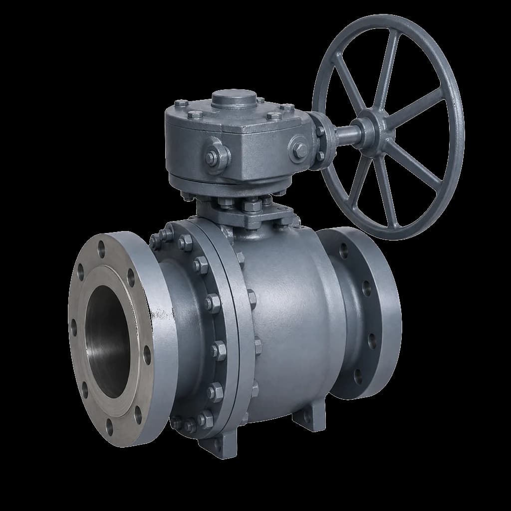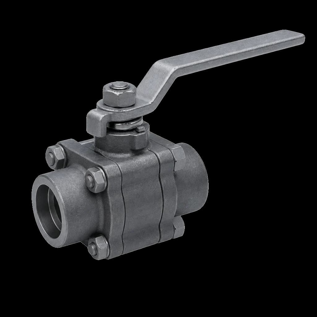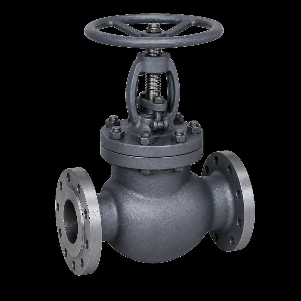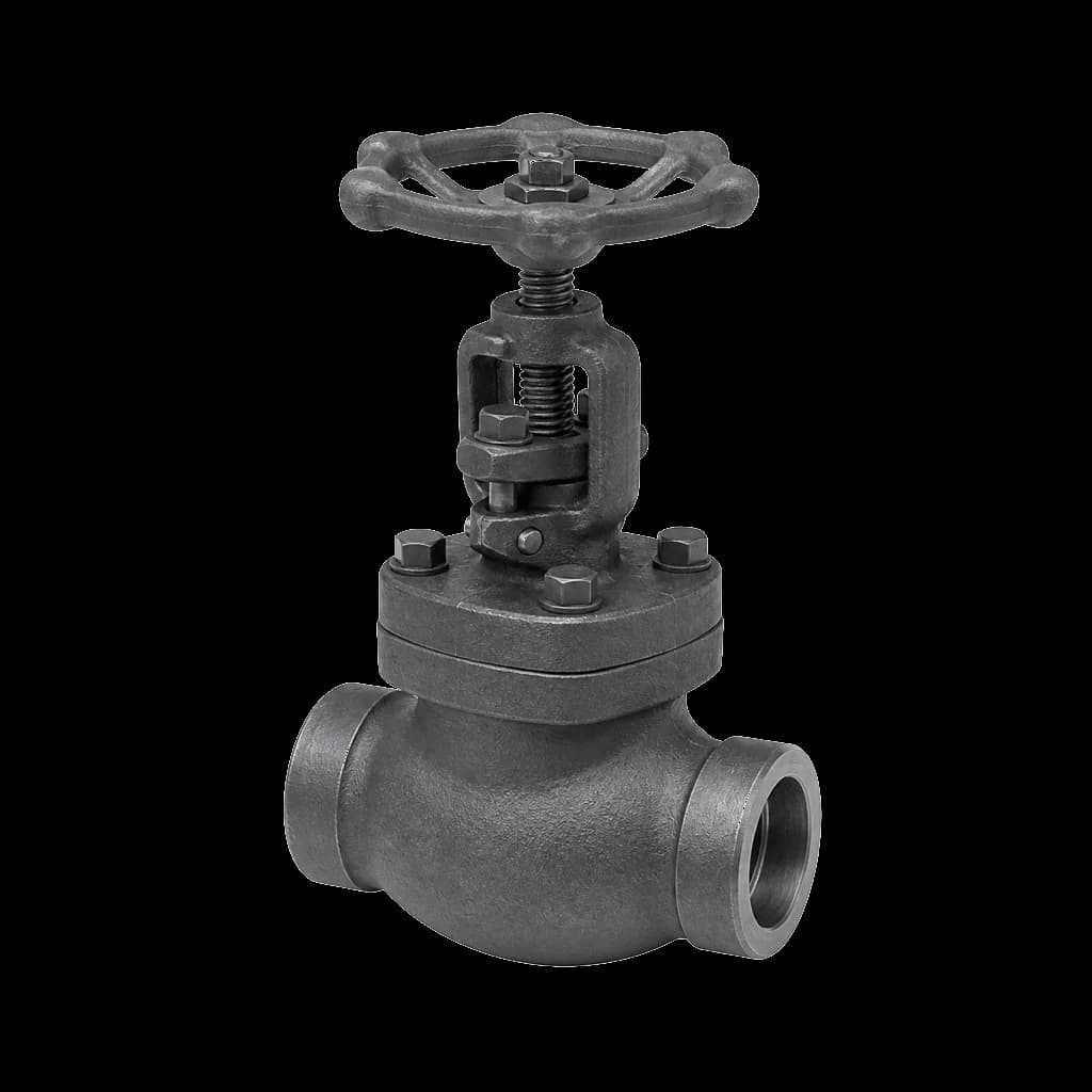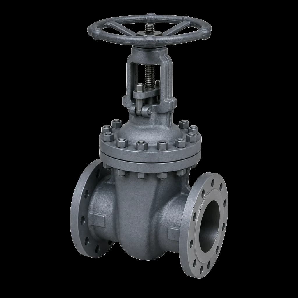
A cryogenic valve is not a stainless valve with a longer bonnet. Once the fluid is cold enough the failure modes change: carbon steel bodies lose toughness, PTFE seats shrink off the ball, gland packing ices over, and liquid trapped in a closed body cavity becomes a pressure source as it boils. LNG terminals, LCNG stations and air separation units run on valves specified against those failure modes at datasheet stage. The alternative is meeting them at commissioning, when the frost pattern on a bonnet neck tells you what you bought.
What makes a cryogenic valve different
Where cold becomes cryogenic depends on the standard. BS 6364 treats service below −50 °C as cryogenic and is the document most Indian tenders name; physicists reserve the word for below −150 °C. The useful line is the one below which a plain carbon steel body and a plain PTFE seat stop working, and that sits close to −50 °C.
| Fluid | Boiling point | Valve scope |
|---|---|---|
| Propane / LPG | −42 °C | Low-temperature carbon steel |
| Ethylene | −104 °C | 3.5% Ni to −101 °C, else austenitic |
| LNG (methane) | −162 °C | Austenitic stainless, extended bonnet |
| Liquid oxygen | −183 °C | Austenitic stainless, oxygen-cleaned |
| Liquid argon | −186 °C | Austenitic stainless, extended bonnet |
| Liquid nitrogen | −196 °C | Austenitic stainless, extended bonnet |
- Toughness. Ferritic and martensitic steels have a ductile-to-brittle transition; austenitic stainless does not, and holds impact energy to −196 °C and below. That one fact decides most of the material selection.
- Differential contraction. Cooling to −196 °C shrinks austenitic stainless by roughly 0.3% and a PTFE seat ring by around 2%. No metal-to-polymer interference fit survives that gap unplanned.
- Expansion on boiling. One volume of LNG becomes roughly 600 volumes of gas at ambient, and liquid nitrogen around 700. Trapped liquid is stored pressure.
- Ice and heat leak. Leak paths fill with frozen moisture that jams stems and props seats open, and every joule conducted down a neck becomes boil-off gas.
The extended bonnet and the vapour column
The defining feature is the extended bonnet: a thin-wall austenitic neck between body and gland. Clearing the insulation is the least of what it does. A stagnant column of cold vapour stands in the neck above the liquid, and that column is the insulator, holding the packing box near ambient while the body sits at −162 °C. Let liquid reach the packing and the chevrons go glass-hard, the stem ices and the gland leaks. On liquid oxygen, that leak into oily lagging is a fire.
How long is long enough
Extension length runs from the body-to-bonnet joint to the gland face and depends on design minimum temperature, size, insulation thickness and whether the line is vacuum-jacketed. MSS SP-134 tabulates minimum extensions and BS 6364 sets the intent, but manufacturers' tables disagree. Do not copy a length off another job: state the temperature, medium and insulation thickness, and make the vendor confirm it against their own range chart.
Orientation is part of the specification
The vapour column only works if it sits still. Install the valve stem-vertical; most cryogenic specifications allow no more than 45° off vertical, and tilt it further and liquid runs up the neck, the column collapses and the gland freezes. A horizontal stem is a design change, not a site adjustment. The neck is deliberately thin to limit conduction, so any gear operator or actuator hung off it needs a bending check.
Body, bonnet and bolting materials
For true cryogenic duty the answer is austenitic stainless: A351 CF8M or CF3M castings and A182 F316 or F316L forgings. Solution-annealed, these grades carry an impact-test exemption down to −196 °C under the ASME B31.3 low-temperature rules, subject to the conditions the code attaches, and they stay ductile below that. The forging grade families behave as they do warm — see A105 and A182 forged valve materials.
The warm end of the same plant is where low-temperature carbon steel belongs, and where most specification errors happen: A352 and A350 grades are impact tested at defined temperatures, and those are limits, not suggestions. ASME B16.34 also gives no credit for cold — below −29 °C the rating is capped at the −29 °C value.
| Material | Form | Spec | Impact test temperature | Typical use |
|---|---|---|---|---|
| CF8M / CF3M | Casting | A351 | Suits −196 °C | Cryogenic body and bonnet |
| F316 / F316L | Forging | A182 | Suits −196 °C | Small-bore bodies, necks |
| LCB / LCC | Casting | A352 | −46 °C | LPG, ammonia, warm boil-off |
| LC2 (2.5% Ni) | Casting | A352 | −73 °C | Cold intermediate duty |
| LC3 (3.5% Ni) | Casting | A352 | −101 °C | Ethylene, refrigeration |
| LF2 / LF3 | Forging | A350 | −46 °C / −101 °C | Forged bodies, flanges |
| B8 / B8M studs | Bolting | A320 | Code dependent | Stainless assemblies |
Two rules are not negotiable. Grey and ductile iron have no business below zero — no CI sluice valve, no DI butterfly valve, whatever the utility drawing says. And bolting must match the service: A320 Gr L7 with A194 Gr 4 or 7 nuts covers the low-temperature carbon steel range, while austenitic A320 B8 / B8M with A194 Gr 8 / 8M nuts goes cryogenic. Gaskets: spiral wound, 316L windings, PTFE filler.
Seats, seals and packing at −196 °C
Virgin PTFE is the wrong cryogenic seat: it contracts far more than the stainless retainer and cold-flows under load, so it reaches temperature with its interference gone. PCTFE is the workhorse soft seat, holding compressive strength and dimensional stability at LNG and LN2 temperatures with low permeability. PEEK keeps its shape better but is hard, demanding higher seating force and a finer finish. Compare them in our valve seat materials guide.
- Spring-energised lip seals — a PTFE or PCTFE jacket over a 316 or Elgiloy spring — answer differential contraction by keeping the lip loaded as the polymer shrinks. Specify them by name; do not assume.
- Metal seats belong on high-cycle duty, dirty boil-off gas and anywhere a soft seat is a fire risk. LNG isolation is often required cryogenic *and* fire-safe: soft primary seat, metal secondary, and neither implies the other.
- Stem sealing is a warm-gland problem by design — PTFE V-rings live-loaded through Belleville washers, or graphite where fire-safe certification is demanded. Thermal cycling relaxes an unloaded gland.
- Cleanliness governs oxygen service: clean to an ASTM G93 level, no hydrocarbon lubricant anywhere, delivered bagged and sealed.
Cavity relief on cryogenic ball valves
Cavity relief is the line item most often missed on an RFQ, and the one that bursts valves. Close a two-seat ball valve on a cold line and liquid is trapped in the body cavity; heat leaks in, it boils, and with a six-hundredfold volume ratio the cavity runs past the body rating. Every cryogenic ball valve needs a defined relief path, and you must say which one:
- A vent hole through the ball, drilled on the upstream face so the cavity relieves into the line when closed. Cheap and reliable, but the valve becomes unidirectional — arrow-marked, installed one way round — and it destroys any claim to double block and bleed.
- Single-piston-effect seats on a trunnion valve, which relieve the cavity into the line automatically while the valve still seals from either end — the usual route on larger API 6D ball valves, and what that standard means by double block and bleed.
- An external cavity relief valve piped to the upstream line or a vent header, needed wherever a double-piston-effect seat is specified for double isolation and bleed, since a DPE seat cannot relieve the cavity itself.
Gate valves face the same arithmetic: a closed wedge traps liquid between its seats, so cryogenic gates carry a relief hole in the upstream disc face or an external body vent. If the datasheet is silent, the vendor picks whatever is cheapest to machine.
Gate, globe and check valves in cold lines
Ball valves dominate cryogenic isolation but are not the whole scope. Globe valves take throttling, filling and drain duty, and bellows-sealed globes go where stem emission must be effectively zero. State the flow direction and let the manufacturer confirm plug and seat orientation: differential contraction at temperature decides whether the valve shuts off, and only a cryogenic type test proves it.
- Gate valves for cold isolation should be OS&Y rising stem with a bolted extended bonnet. Never an inside-screw non-rising stem — a stem thread running in cryogenic liquid galls and ices. And do not throttle it; a part-open gate wire-draws the seat exactly as it does in steam.
- Check valves need austenitic or Inconel X-750 springs and pins and a seat that holds shape cold — metal or PCTFE, never plain PTFE. Dual-plate wafers save weight, but confirm the type test covers the clamped wafer body.
- Butterfly valves in triple-offset, metal-seated form are the large-bore answer where a ball valve becomes unliftable. Concentric rubber-lined valves have no place in cold service: the elastomer goes hard and shrinks off the disc.
Cryogenic valve testing and certification
Cryogenic valve testing happens in two stages, and buyers routinely pay for the first while assuming the second. First the ambient shell and seat tests to API 598, on every valve. Then the cold type test on a representative valve, to BS 6364, MSS SP-134 or ISO 28921-2, with ISO 28921-1 governing design and production testing.
That test mounts the valve in its service orientation, immerses the body in a liquid nitrogen bath, holds until temperatures stabilise, cycles it cold a defined number of times, and measures seat and stem leakage in helium collected by water displacement. Allowable rates scale with size and differ between standards, so name the standard *and* the acceptance rate rather than writing "cryogenic tested". Have the breakaway torque recorded cold: it runs well above the ambient figure, and an actuator sized warm will stall.
- Charpy V-notch impact tests at or below the design minimum temperature for every pressure-containing part the code does not exempt.
- PMI on body, bonnet, extension neck and trim — the neck is the part most often substituted.
- A type test certificate for the actual design, size and class supplied; a 2" Class 150 certificate does not qualify a 12" Class 300 valve.
- Evidence that hydrotest water was drained and dried, with valves despatched dry, purged and end-capped.
- EN 10204 3.1 certificates minimum, 3.2 where the tender demands it, with hydro and type test reports in one dossier.
What the datasheet must state
Indian demand is no longer niche. The terminals at Dahej, Hazira, Kochi, Ennore and Mundra, the LNG road-tanker and LCNG chain feeding PNGRB-licensed city gas networks, and air separation units at every large steel and fertiliser plant buy against EIL, MECON or consultant specifications with third-party inspection. Those specifications are won or lost on the datasheet.
- Fluid, phase and design minimum temperature — including blowdown and upset cases, not just normal operating.
- Design pressure and class; body, bonnet, neck and trim materials with the impact test requirement spelt out.
- Extension length basis, insulation thickness and the permitted stem orientation envelope.
- Seat material, ambient seat leakage class, and the accepted cryogenic leakage rate with its standard.
- Cavity relief scheme, and flow direction on the P&ID if the ball is vented.
- End connections — butt weld preferred, with schedule and bevel; keep threaded joints out of the cold box.
- Operator sized on cold torque, fire-safe requirement, oxygen cleanliness level, and an ITP with hold points.