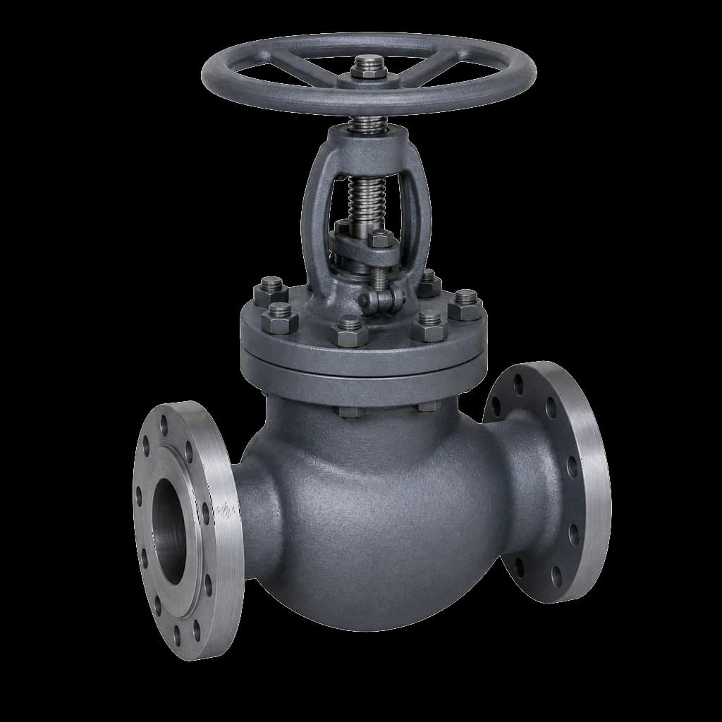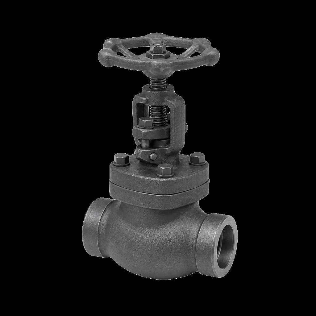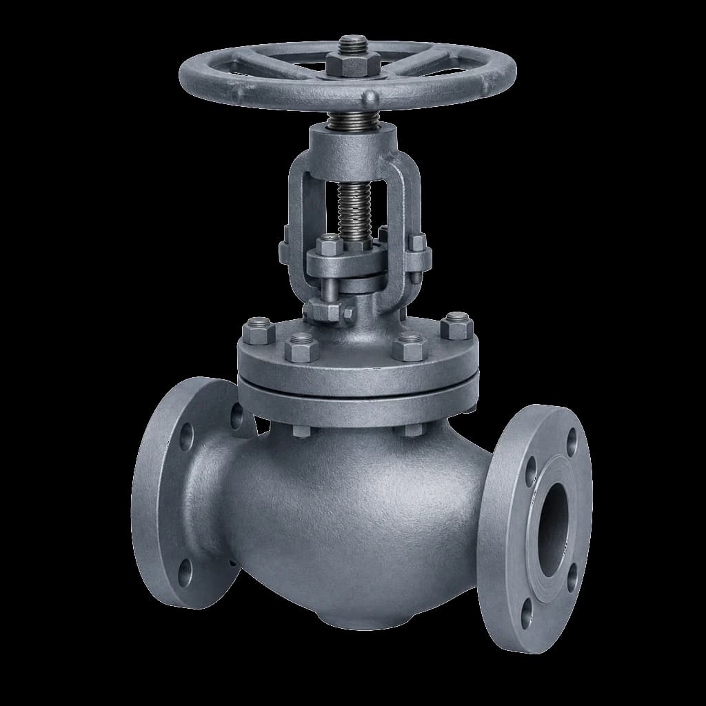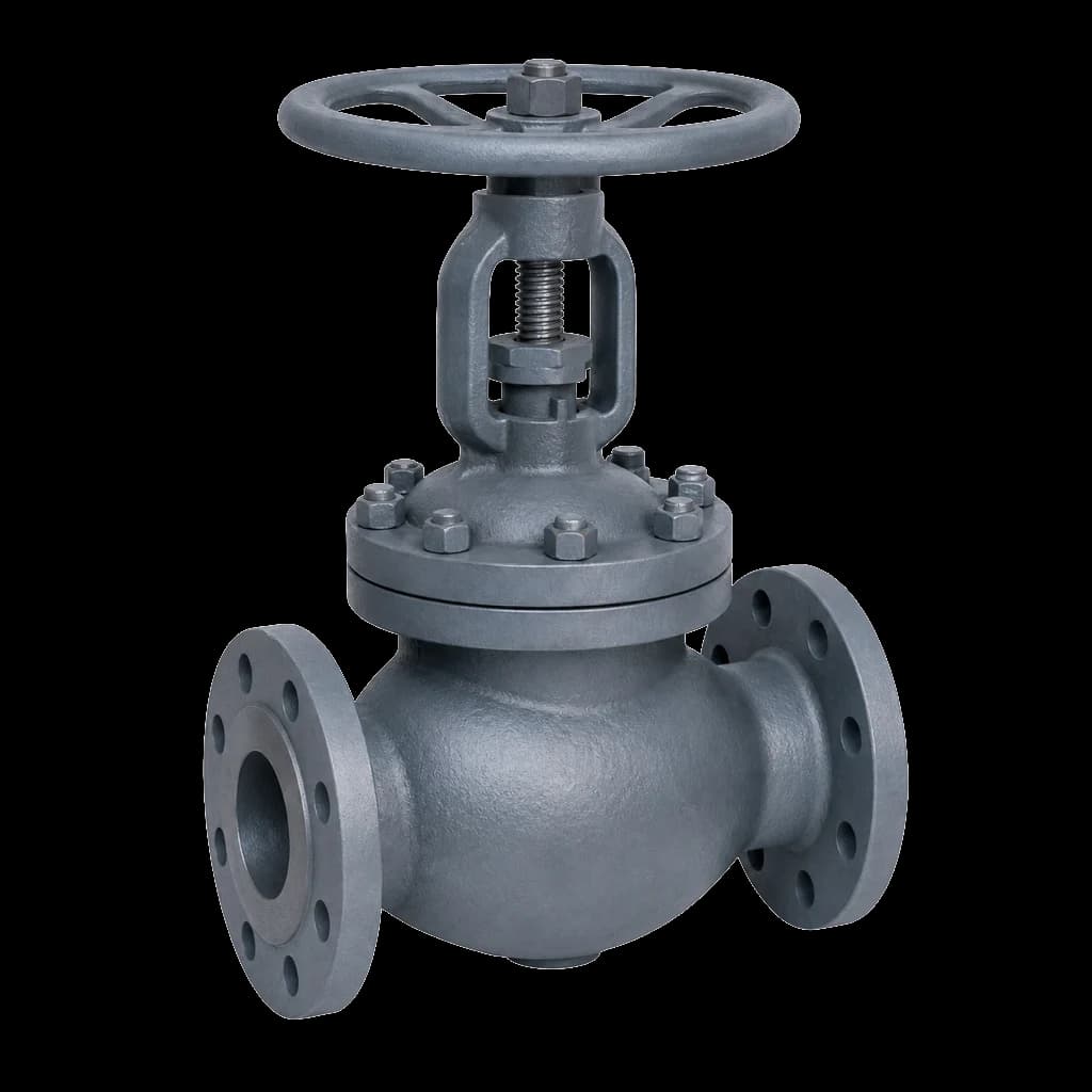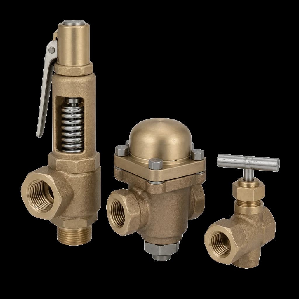
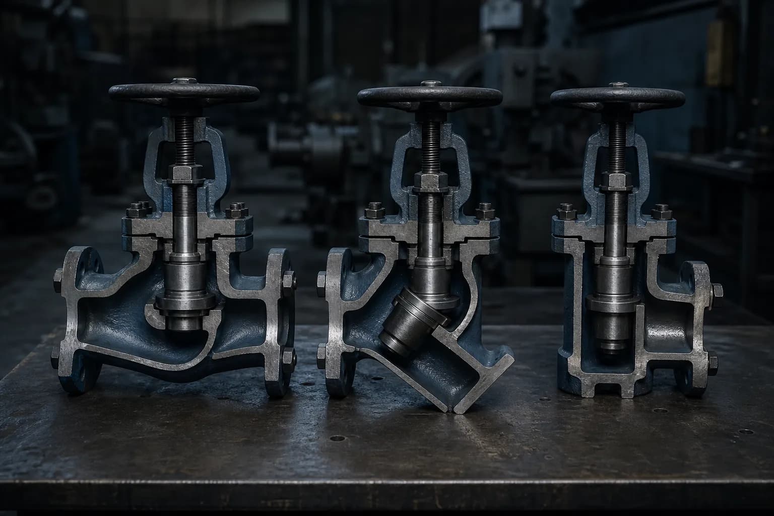
A globe valve regulates by driving a disc onto a seat that sits square across the flow, and that geometry is what makes it the throttling workhorse on steam, feedwater and dosing lines. What most specifications never state is which of the three types of globe valve body is wanted — T-pattern, Y-pattern or angle. The line item says 2" globe valve, Class 300, WCB, flanged, the vendor ships the standard catalogue item, and the standard catalogue item is almost always a T-pattern. Often that is the right valve. When it is not, the plant has bought either a permanent pressure drop the pump pays for every running hour, or an elbow and a joint that never needed to exist.
The three types of globe valve body pattern
All three patterns work identically at the seat: linear stem motion, a disc landing perpendicular to the seating face, and shutoff that tightens as you push harder. The difference is where the seat sits relative to the run of pipe — and resistance, Cv, face-to-face, headroom, cost and repairability all fall out of that one choice. If the choice is still between valve families rather than patterns, settle that first with gate vs globe vs ball valves.
T-pattern (Z-body): the default that ships unless you ask
The seat lies horizontal; flow enters, turns up through the seat, turns again and leaves — the classic Z path. Full open, it is the most resistive of the three patterns and one of the most resistive components you will bolt into a line. In exchange you get the shortest face-to-face of the three patterns in ASME B16.10, the simplest casting, the widest availability across every class and material, and the easiest field repair, since the seat is accessible straight down the bonnet bore for in-situ lapping. On short runs, small bore and any line where a few hundred millibars of loss is irrelevant, the T-pattern is not a compromise. It is the right answer.
Y-pattern: the seat tilted out of the flow path
Tilt the stem and seat away from the run — commonly 45 degrees, and 60 degrees in some designs — and the fluid passes almost straight through with one gentle deflection instead of two right angles. Pressure drop at a given flow falls to roughly half that of the equivalent T-pattern, and 60-degree constructions do considerably better than that. You pay in face-to-face length, casting weight and cost, and in something people forget until the pipe is in the rack: the bonnet and stem project at an angle, so handwheel clearance and gland access must be checked on the isometric, not assumed. The Y earns its keep on boiler feed, continuous blowdown, high-differential throttling, and any line that stays open and is trimmed often.
Angle pattern: the valve that deletes an elbow
An angle body takes the fluid in horizontally and discharges it vertically — the valve is the 90-degree turn. That removes a long-radius elbow and one flanged or welded joint from the layout: one less leak path, one less weld to radiograph, less installed length in a congested rack. Hydraulically, an angle globe on its own beats a T-pattern globe plus an elbow. It is the conventional choice at header take-offs, tank and vessel nozzles, blowdown and drain points, and erosive service where the discharge should leave straight down the pipe instead of impinging on a body wall. In stop-check (screw-down non-return) form it is also a standard pump-discharge valve.
What the body pattern costs in pressure drop
Valve resistance is published two ways: as a flow coefficient Cv, which manufacturers tabulate per size, and as a resistance coefficient K, which the Crane TP-410 method expresses as a multiple of the pipe friction factor fT. The two are linked — head loss scales with K, while Cv scales with one over the square root of K — so halving K lifts Cv by about 1.4 times, and cutting K to a sixth roughly two-and-a-half times it. The values below are Crane's published ones for fully open valves. Treat them as a shape, not as input to a hydraulic calculation.
| Valve / pattern | K (multiples of fT) | Relative Cv | Comment |
|---|---|---|---|
| Globe, T-pattern (Z-body) | ≈ 340 | 1.0 (baseline) | Two right-angle turns |
| Globe, Y-pattern, stem at 45° | ≈ 150 | ≈ 1.5× | About half the head loss |
| Globe, Y-pattern, stem at 60° | ≈ 55 | ≈ 2.5× | Near-straight passage |
| Angle globe, unobstructed seat | ≈ 55 | ≈ 2.5× | Deletes an elbow as well |
| Gate valve, full open | ≈ 8 | — | Scale only; not for throttling |
| Full-bore ball, full open | ≈ 3 | — | Scale only; on-off duty |
Two conclusions follow. On a line that runs wide open and is regulated only occasionally, the pattern is an energy decision: the gap between K of 340 and K of 150 on a large feedwater line is head the pump has to deliver every hour the plant runs, and it lands on the motor's energy bill rather than on the purchase order. On a line that is normally throttled well off its seat, the pattern matters far less than the trim, because the seat restriction at part lift dominates the body geometry entirely.
Flow under the seat, or over it
Every globe body has a preferred direction, marked with an arrow, and it is not decoration. Flow under the seat — pressure arriving beneath the disc, tending to lift it open — is conventional for general service. Its practical advantage is maintenance: with the valve shut, the bonnet and gland sit on the low-pressure downstream side, so packing can be attended to while the upstream line stays live. The cost is that closing works against the fluid, and the disc can chatter near the seat at high differential.
Flow over the seat reverses both. Pressure assists seating, the disc stays stable as it approaches shut, and the valve closes quietly and tight — which is why high-pressure, high-temperature steam stops are often arranged this way, usually with a bypass valve because opening against full differential is heavy work. The penalty is a gland that is live whenever the valve is closed. Practice differs between makers and specifications, so do not reason it out on site: follow the body arrow, and if the piping forces the opposite direction, raise it with the vendor before the valve ships. The class, trim and IBR consequences for steam are worked through in our steam service valves guide.
Disc and trim decide the throttling duty
Body pattern sets the hydraulics; the disc decides whether the valve survives being throttled. Four forms cover almost everything you will specify.
| Disc form | Does well | Do not use for |
|---|---|---|
| Plug / parabolic taper | Sustained throttling; the long seat land resists wire-drawing and gives finer control near shut | Plain on-off duty, where a ball disc does the same job for less |
| Ball / spherical disc | On-off and infrequent regulation; cheapest; tight on clean fluid | Continuous throttling; the narrow land wire-draws and never seals again |
| Composition (renewable soft insert) | Bubble-tight shutoff on water, air and mild service; the insert is replaced in the field without lapping the seat | Steam, hot oil, anything past the insert's temperature rating |
| Needle (small bore, instrument) | Gauge isolation, sampling, dosing and calibration lines; fine metering | Any duty needing real flow capacity |
Materials follow the same logic as gate valve trim numbering: 13 percent chromium stainless (410) for general service, austenitic 316 where corrosion drives it, and cobalt-alloy hardfacing on seat and disc face wherever wet or throttled steam is involved. Hardfacing is the one upgrade worth arguing for on a regulating globe, because the failure it prevents — wire-drawing across a nearly-closed seat — cannot be repaired in the field. Pair it with die-formed graphite packing, never PTFE, at steam temperature. The full trim map is in our valve trim materials guide.
Matching the pattern to the duty
- Steam warm-up and main-stop bypass: T-pattern, hardfaced plug disc, rated to the class of the main line rather than to the small bore of the bypass. Throughput is low, seat survival is everything, and the short face-to-face suits a tight bypass loop.
- Boiler feed regulation and recirculation: Y-pattern, hardfaced trim, with the class set by the feed pump's shut-off head rather than by the drum pressure. The classic Y duty — high differential, high velocity, line normally open. Read it with boiler feed check and blowdown valves before fixing the valve schedule.
- Continuous and intermittent blowdown: angle pattern at the drum take-off with hardfaced plug trim. It deletes the nozzle elbow and lets flashing discharge leave straight down the pipe.
- Dosing, sampling and gauge isolation: small-bore forged bodies, needle or plug disc, socket-weld or screwed ends — DL forged globe valves cover this range from 1/2" upward.
- Cooling water and utility isolation: T-pattern cast body, ball or composition disc. Do not pay for a Y here; the differential rarely justifies it.
- Pump or boiler discharge into a common header: stop-check (SDNR) globe, T or angle body. The disc rides free on the stem, so one valve throttles, stops and prevents reverse flow — expected practice where several machines feed one header.
Sizing, and the mistakes that reach us on RFQs
Size a globe on required Cv, not on line size. Sized by line size, a regulating globe spends its life barely off the seat, and that is exactly where seats are destroyed: the flow is forced through a narrow annulus at high velocity and wire-draws the seating faces. Keep normal duty in the broad middle of the travel; if the hydraulics will not allow it, specify a reduced-port or reduced-trim globe rather than a large valve you will never open.
- No pattern in the line item. You will be quoted a T-pattern. If the duty wanted a Y or an angle, nobody downstream will tell you — name the pattern in the enquiry.
- Treating a globe as a control valve. A hand-operated globe has no characterised trim, no positioner and no defined installed characteristic. Modulating loops take a control valve; the globe does manual regulation and isolation.
- Y-pattern headroom left unchecked. The inclined bonnet needs stem-withdrawal clearance at an angle. A drawing-office check costs less than a re-route.
- Forgetting that a globe is a one-way device. Reverse flow at pressure can slam or unseat the disc. Check the arrow against the actual flow direction, not the intended one.
Standards and what the RFQ line item must state
Cast steel globe valves are supplied to API 623 or BS 1873; compact forged globe valves in NPS 4 and smaller follow API 602; bronze and gunmetal globe valves for water service follow IS 778. Face-to-face comes from ASME B16.10, pressure-temperature rating and minimum wall from ASME B16.34, and shell and seat testing is normally to API 598. Boiler-connected steam lines inside IBR scope need Form III-C certification with the valve.
- Size, pressure class and ends — flanged to ASME B16.5 with the facing stated, butt-weld with schedule, or socket-weld and screwed for forged bodies.
- Body pattern: T, Y or angle — and for angle bodies, which leg is the inlet.
- Body and bonnet material — A216 WCB, A217 WC6 or A351 CF8M cast, A105 or F316 forged — with the trim designation and whether hardfacing is required.
- Disc form, bonnet type (bolted, or pressure-seal from Class 900 upward), packing material, and operator — handwheel, gear or actuated.
- Documentation: API 598 shell and seat test, EN 10204 3.1 or 3.2 MTC, hydro test report, and IBR Form III-C where the line is boiler-connected.