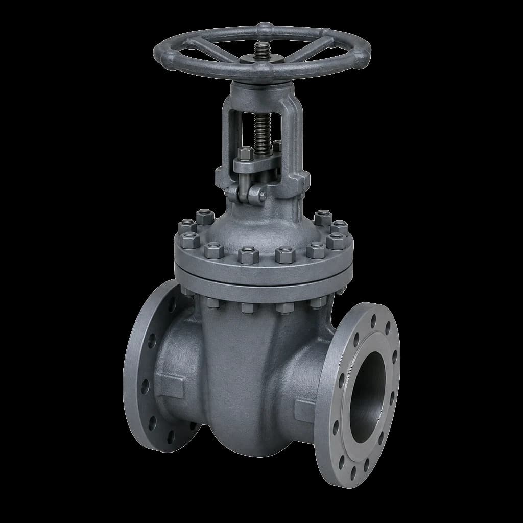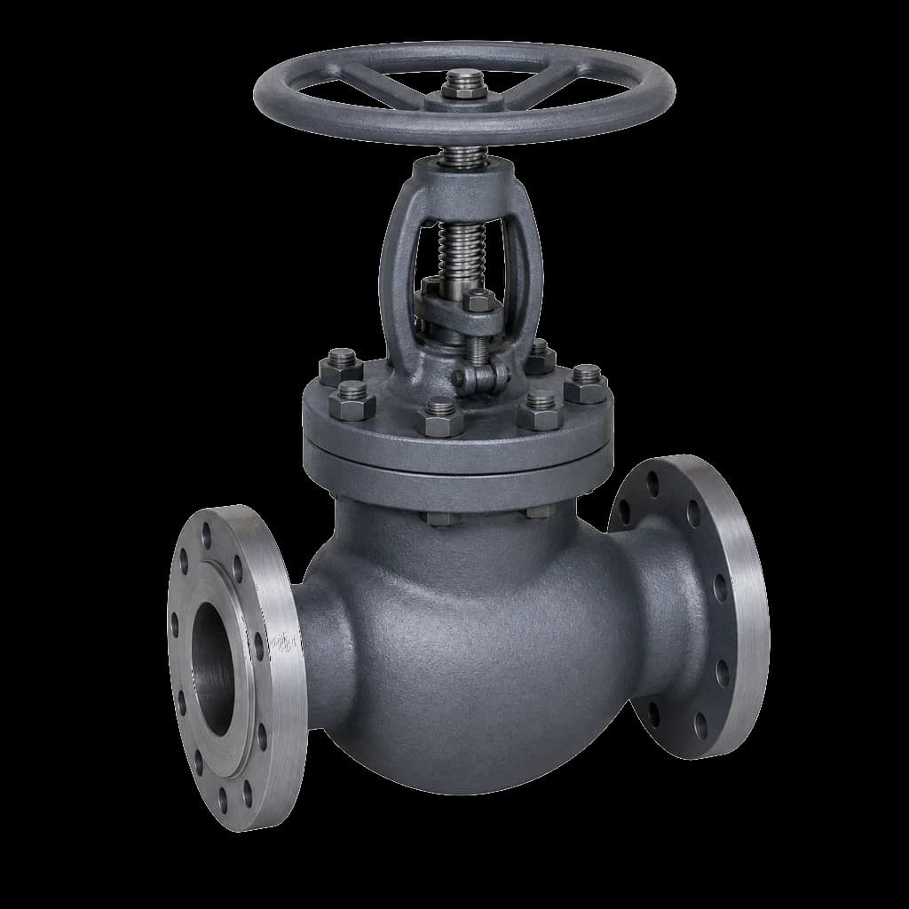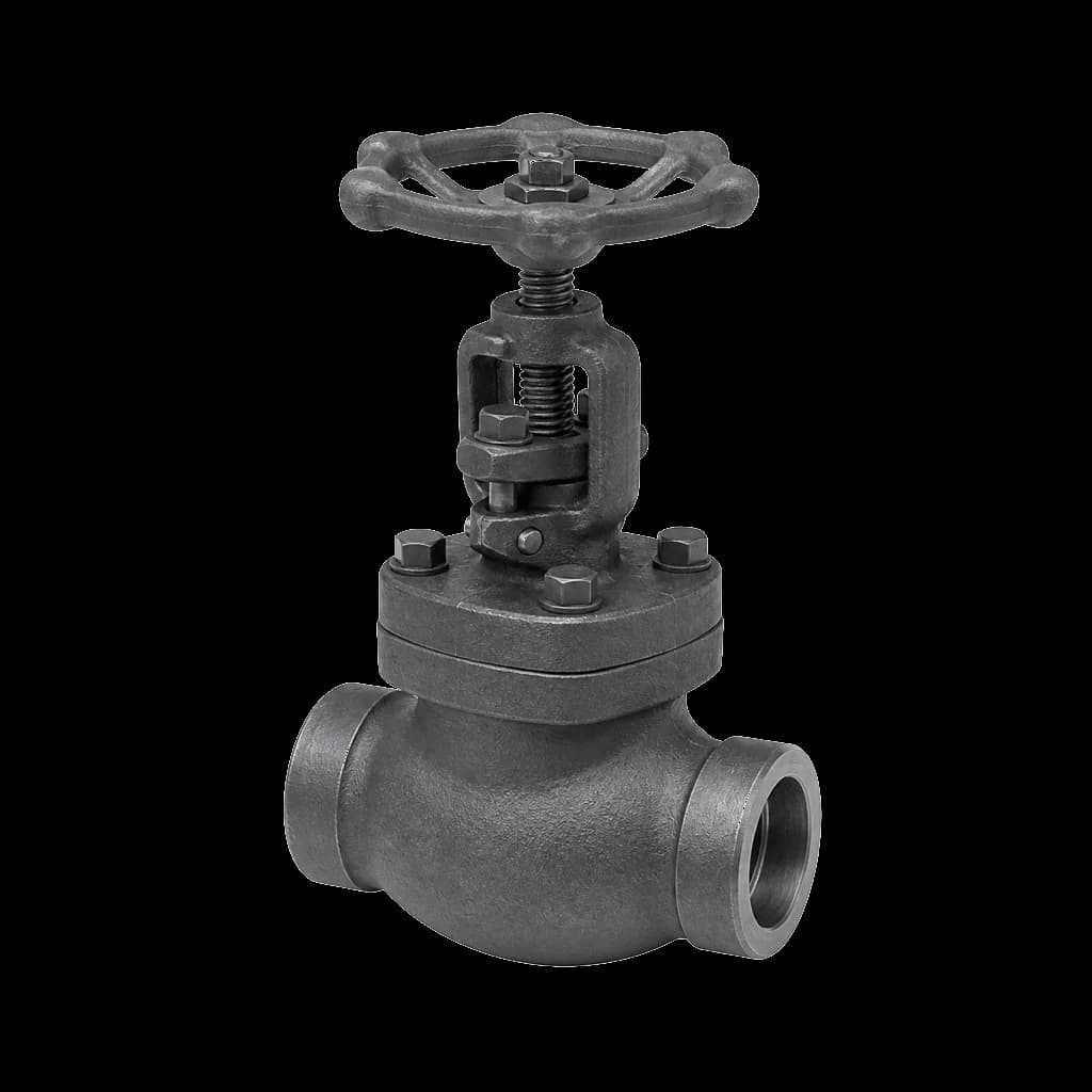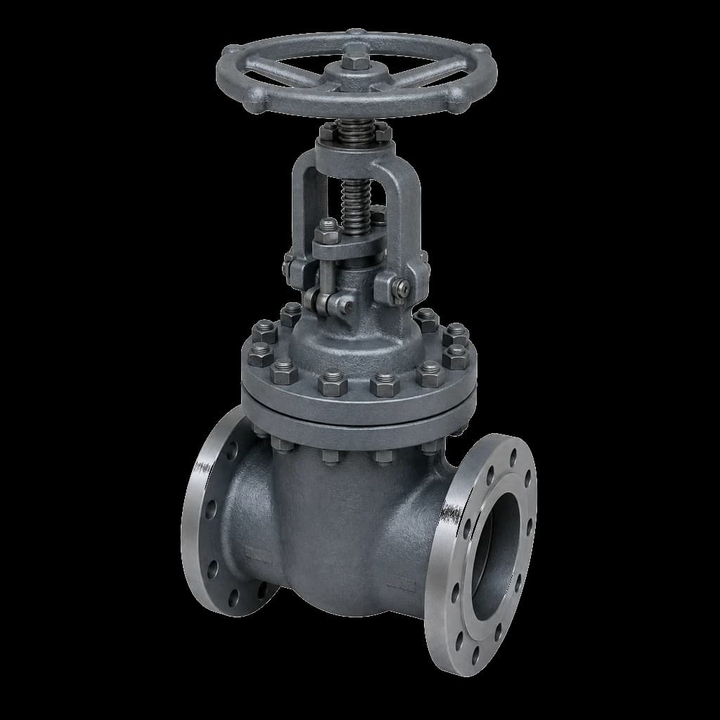
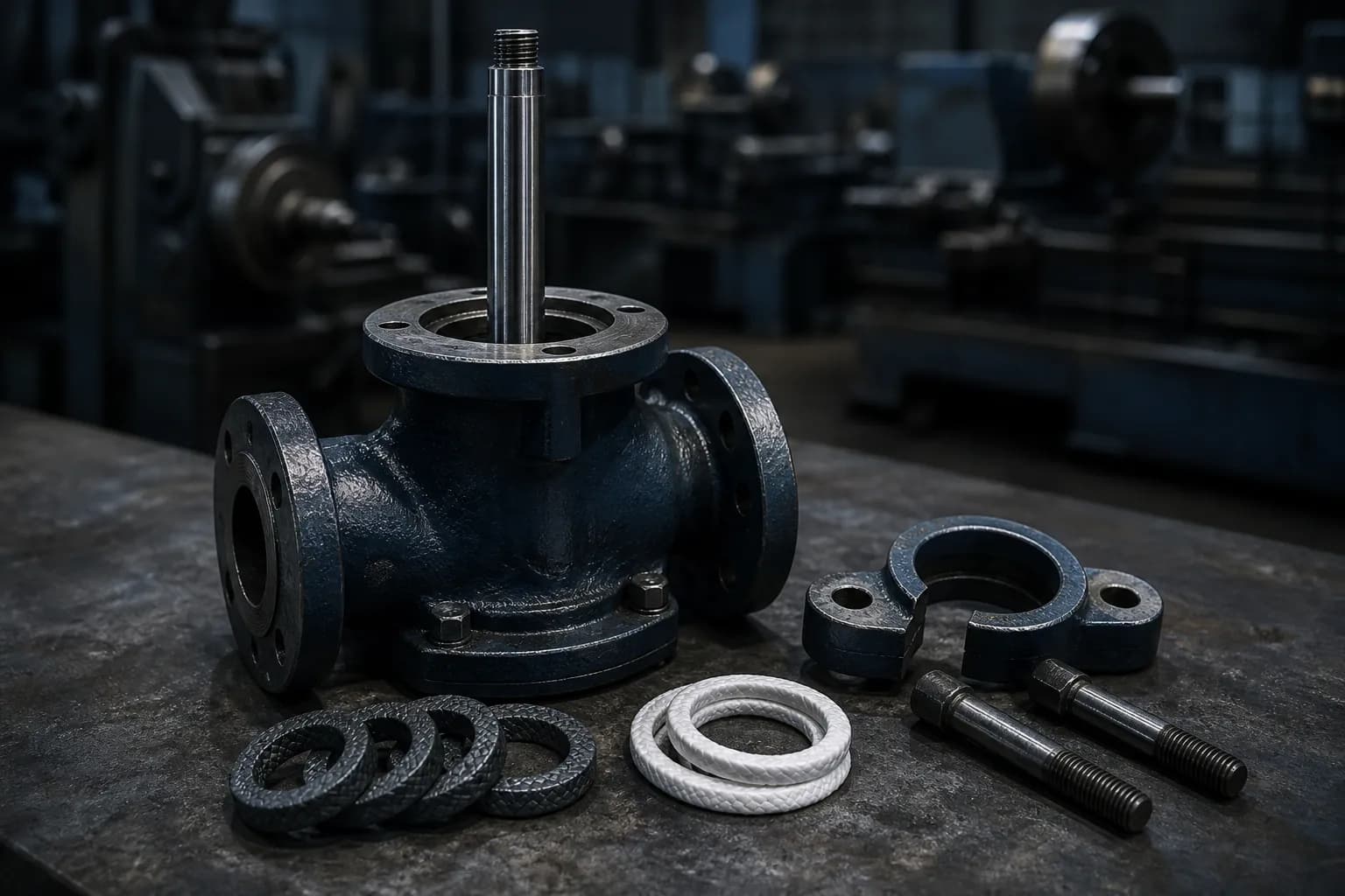
Valve gland packing is the least glamorous part of a valve and generates the most work orders. A stem weeping at the gland rarely means the valve is finished — the set was wrong for the duty, badly installed, or tightened past the point where it can seal. This covers graphite against PTFE, sizing a set from the box, cut sequence, gland stud torque, live loading, and when the packing is not the problem at all.
How valve gland packing seals in a stuffing box
Gland studs apply an axial load, the packing behaves like a stiff plastic solid, and part of that load becomes radial stress against stem and box wall. That radial stress is the seal, and it must still exceed line pressure at the stem after the set consolidates and after the first thermal cycle. Die-formed graphite makes that conversion efficiently, sealing at a lower gland load than braided packing of the same section.
Why the top rings do most of the work
Load does not travel down the box evenly: each ring bleeds part of it into the wall as friction, so the top ring or two carry most of the seal. Adding rings buys stem friction, not sealing, eating into a gearbox or actuator's margin. Four to six rings suits almost every isolation valve.
Types of gland packing and where each belongs
The types of gland packing used in valves reduce to two families: graphite for heat, PTFE for chemistry. Most bad decisions start by ignoring that split.
Die-formed flexible graphite
Die-formed rings are pressed from exfoliated graphite tape to a controlled density in a die matched to the stem and box, so they arrive at size. Flexible graphite runs from cryogenic to roughly 650 °C in steam and non-oxidising service; in air it oxidises from around 450 °C, which governs the top ring. It is the default for steam, hot oil, fire-safe valves and any emission clause. Graphite is also cathodic to stainless steel, so specify inhibited, low-halide grades on stainless stems. API 600 calls up flexible graphite packing for cast steel gate valves as standard; weighing API 600 against API 602 forged valves, read both packing lines rather than assume they match.
Braided carbon and graphite yarn
Braided carbon or graphite yarn rings are the anti-extrusion end rings of a graphite set, not the bulk of it: one at the bottom, three die-formed between, one under the follower. Substituting all-braided rings because that is what the store held is why a valve leaks again a month later.
PTFE, filled PTFE and V-ring sets
PTFE is the chemical answer, not the thermal one. Braided PTFE serves from cryogenic to about 260 °C and is inert across the whole pH range — acids, caustic, DM water, food-grade duty. Its weakness is creep: it cold-flows under load, so the set relaxes and needs re-torquing after commissioning. Filled and expanded grades creep less but do not raise the ceiling, and none is a steam packing. V-ring stacks belong on control valves and cryogenic bonnets, where stack height and preload are design values.
| Packing | Temperature | Typical duty | Watch out for |
|---|---|---|---|
| Die-formed flexible graphite | ~650 °C in steam; ~450 °C in air | Steam, hot oil, fire-safe, emission service | Pits stainless stems if halides present |
| Braided carbon or graphite yarn | As flexible graphite | End rings of a die-formed set | Needs more gland load than die-formed rings |
| Braided PTFE | -200 to 260 °C | Acids, caustic, DM water, pharma | Cold flow — re-torque after commissioning |
| Filled or expanded PTFE | -200 to 260 °C | Chemical duty needing less creep | PTFE ceiling — never for steam |
Sizing a valve gland packing set
Section is geometry, not preference: section = (stuffing box bore − stem diameter) ÷ 2. Measure the bore low in the box where the follower has not worn it, the stem where packing never touched, and both at two planes 90° apart. Box depth divided by section gives the ring count. Round to a standard section — 5, 6, 8, 9.5, 10, 12.7 and 16 mm cover most Indian stock — and never file or stretch a ring.
| Stem dia (mm) | Section (mm) | Rings | Typical valves |
|---|---|---|---|
| Up to 12 | 5 to 6 | 4 to 5 | 1/2" to 1" forged, Class 800 |
| 12 to 20 | 6 to 8 | 4 to 6 | 1" to 3", Class 150 to 600 |
| 20 to 30 | 8 to 10 | 5 to 6 | 3" to 8" cast steel |
| 30 to 45 | 10 to 12.7 | 5 to 6 | 8" to 16" cast steel gate |
| Above 45 | 12.7 to 16 | 5 to 6 | Large-bore gate, API 6D ball |
- Measure, do not infer. Two valves of the same size and class from different makers often have different box bores; the spares drawing beats the catalogue.
- Count what comes out, lantern ring included, and put that ring back exactly where it was — a buried leak-off or quench connection is a defect, not a detail.
- Record the stem finish. Packing wants roughly 0.4 to 0.8 µm Ra, and a worn throat bush lets the stem wander inside the rings.
Repacking: ring count and cut sequence
Never open a gland on a line under pressure. Isolate, depressurise, drain, cool, lock out. Backseating a gate valve fully open does take line pressure off the packing, but a backseat is a design feature, not a maintenance isolation, and no procedure should treat it as one.
- Strip completely. Extract every old ring with a corkscrew puller; rings left in the box are why a fresh set weeps on the first stroke.
- Inspect the stem before you spend a set. Score marks a fingernail catches in, wear confined to the packing zone, or visible runout mean the stem is the fault.
- Fit one ring at a time, seating each fully before the next goes in, and stagger the joints at least 90° apart. Rings pushed in as a stack bridge in the bore and never seat.
- Leave take-up. A follower flush on the box face at the start means one ring too many.
Gland stud torque: a method, not a number
Nobody publishes a universal gland torque — it depends on box area, packing and stud size. Derive it. Gland force is the packing's seating stress times the annular area of the box, A = π/4 × (bore² − stem diameter²). The maker publishes that stress; practice sets gland stress at roughly 1.5 to 2 times line pressure at the stem. Divide by the number of studs and convert with T = K × d × W, K about 0.2 for as-received threads and nearer 0.15 with anti-seize.
- Bring the follower down square. Nip both nuts finger tight, then measure the follower-to-box gap on opposite sides; a cocked gland wears one side of the stem.
- Tighten in three stages, alternating across the studs at 30, 60 and 100 percent of calculated torque, then stroke the valve and re-check: the set will have lost load, which is normal.
- Adjust in flats, not turns. One flat per nut at a time until weeping stops; then stop, and log the final torque against the valve tag.
Over-tightening is the commonest field error and self-defeating: excess load extrudes packing into the stem clearance, scores the stem, and drives operating torque high enough to stall a gearbox or undersized actuator. If a valve wants more gland load every month, tightening harder is not the answer.
Live loaded packing and when it pays
Live loading replaces the rigid nut with a stack of Belleville disc springs, holding a broadly constant gland load as the packing consolidates and as temperature cycles. On a hot rising-stem gate or globe valve, it is the difference between a set lasting a campaign and one chased with a spanner every shutdown.
- Stack direction sets the behaviour. Nested in parallel, the washers multiply load; alternated in series they multiply deflection — and live loading wants deflection.
- Work the springs well short of flat, so travel remains when the packing consolidates, and match washer material to temperature.
- It is a retrofit, not a redesign. Kits fit existing gland studs on most cast steel gate valves and globe valves, so spend them on chronic leakers. Torque to the specified stack height, never to feel.
When the packing is not the problem
A stem that leaks after a competent repack is not a packing problem. Check these.
- Worn or scored stem. The stem is trim — our valve trim materials guide covers the usual 410, 316 and hardfaced choices.
- Ovalised or pitted box. Corrosion in the bore leaves the packing nothing to seal against.
- Bent stem, usually a cheater bar on a seized valve; runout drags the packing open once per turn.
- Wrong packing for the medium. PTFE on a steam line looks perfect at handover and fails on the first hot cycle.
- Economics. On small forged valves the permit and labour outweigh the valve, so replacing a 1" Class 800 forged gate valve is often cheaper. On large-bore cast steel valves, repacking properly always pays.
On steam and condensate, packing failure rarely travels alone — a weeping gland, a wire-drawn seat and a blowing trap usually share a root cause. Our steam service valves guide covers the combinations that survive there; traps and separators come from the same steam specialities range.
Specifying packing on the PO and in tenders
Half the packing problems on an Indian site are bought, not made. Specify:
- Material and construction explicitly — die-formed flexible graphite with braided carbon end rings, not the word "graphite" — and low-halide grade on stainless stems, with the certificate called in the ITP.
- Asbestos-free, in writing. It is still sold in India and will get an export consignment rejected.
- The emission standard, if there is one. ISO 15848-1, API 622 and API 624 test different things — read what each fugitive emission test proves before copying a clause from an old tender.
- Spare sets with the valve, quoted against the tag and part number. On IBR steam lines, file the packing spec with the valve's Form III-C.