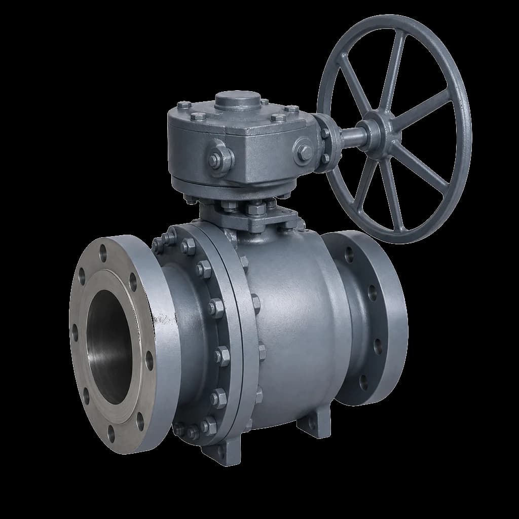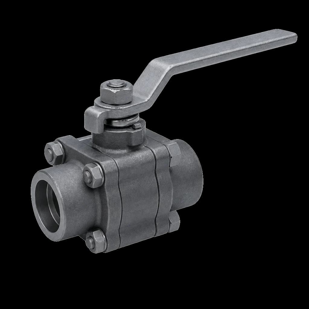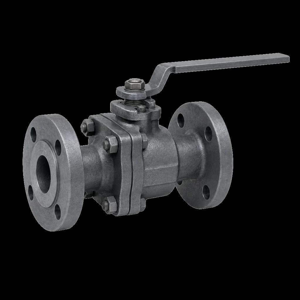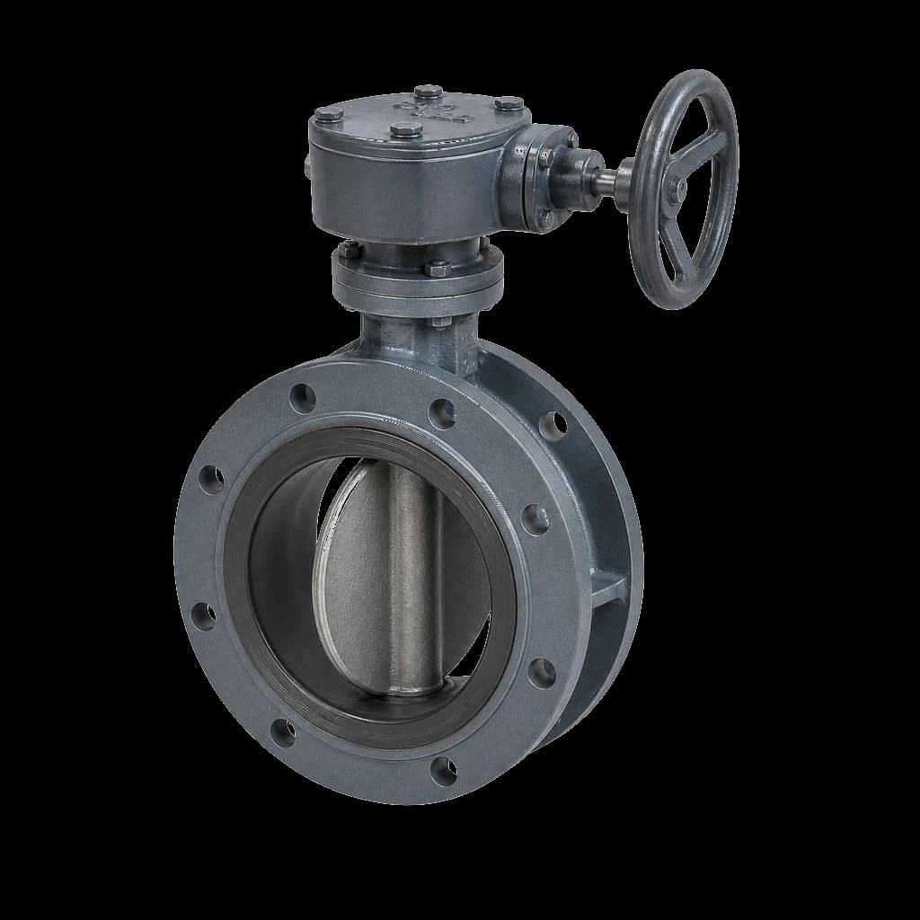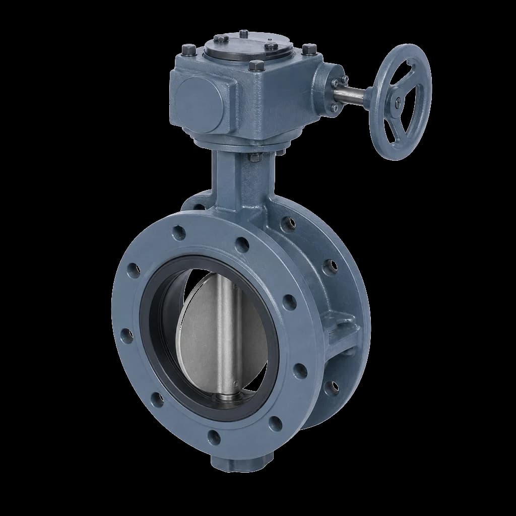
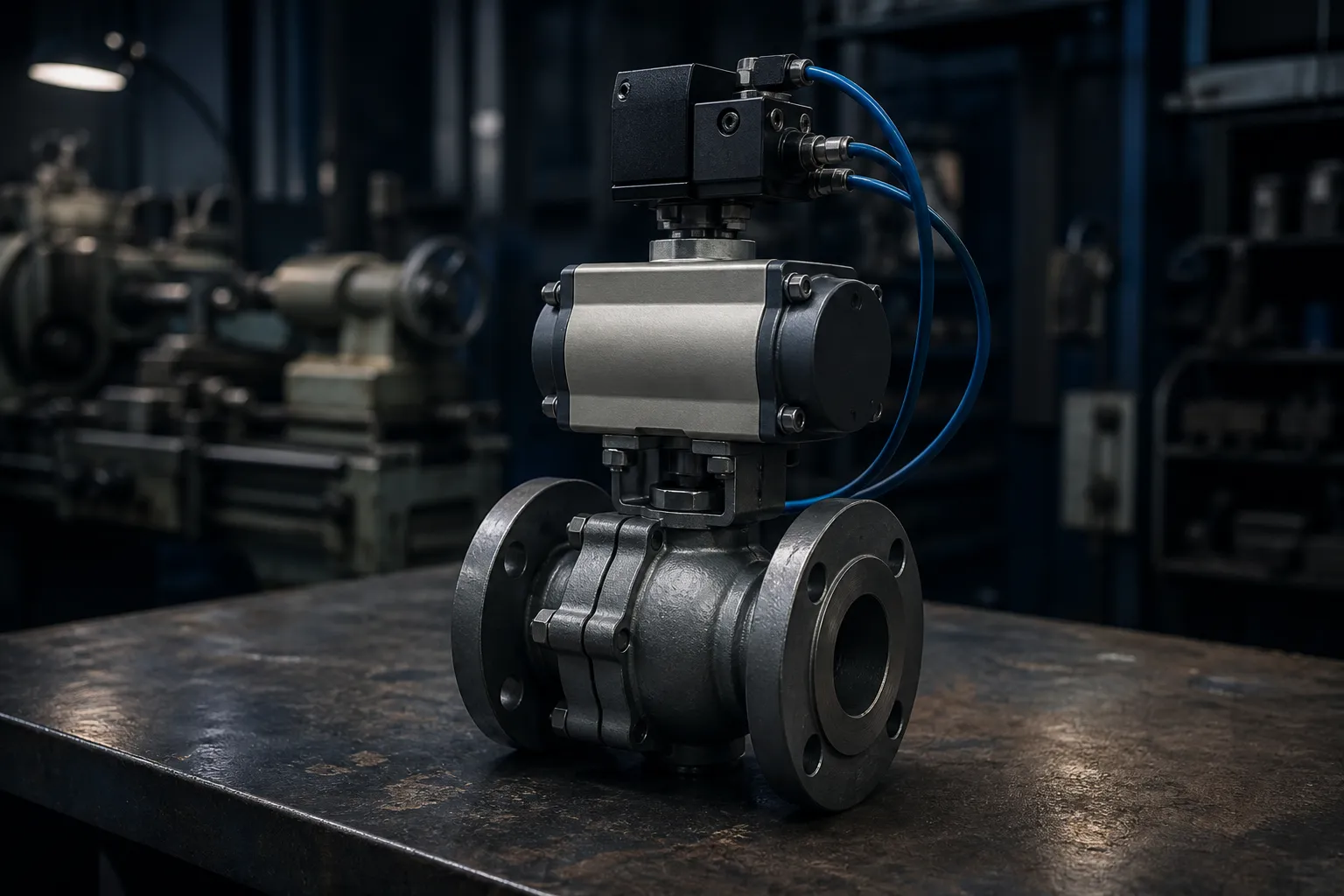
An actuator for a ball valve is two purchase orders that have to agree, placed weeks apart by different buyers. Both arrive, and someone discovers on site that the pad is F05 and the actuator base F07, or that the stem carries a 17 mm square where the actuator wants a double-D. Nothing is defective; nothing can be assembled either. ISO 5211 exists to stop that, and it works only where the interface is written into both specifications.
What ISO 5211 actually standardises
ISO 5211 covers part-turn actuator attachments: the mechanical joint between a quarter-turn valve and whatever drives it — pneumatic or electric actuator, worm gearbox, lever bracket. It fixes two things and leaves the rest open.
The flange (the pad)
The pad is designated F for its bolt circle diameter in millimetres: F05 is a 50 mm PCD, F07 70 mm, F10 102 mm. The standard fixes PCD, thread size and hole pattern — four blind tapped holes on the small and mid flanges, eight on the large ones — and adds a spigot or recess centring the actuator on the stem axis. Miss the matching counterbore and the joint perches on that spigot: screws tight, faces never clamped.
The driving component (the stem end)
ISO 5211 tabulates a lettered drive form alongside each flange. Three dominate on Indian-built valves: a male square engaging a female square in the actuator or gearbox, a double-D with two milled flats, and a keyed round bore. The letter alone is not a specification: transcribe form, across-flats size and — most often missed — the usable engagement length of stem above the pad face, off the valve GA drawing. A coupling bore deeper than the square is long bottoms on the stem and holds the base plate off the pad.
| Flange | Bolt circle PCD (mm) | Fasteners | Stem square (mm) | Commonly seen on |
|---|---|---|---|---|
| F03 | 36 | 4×M5 | 9 | 1/2"-3/4" |
| F04 | 42 | 4×M5 | 11 | 1/2"-1" |
| F05 | 50 | 4×M6 | 14 | 3/4"-1 1/2" |
| F07 | 70 | 4×M8 | 17 | 1 1/2"-3" |
| F10 | 102 | 4×M10 | 22 | 3"-4" |
| F12 | 125 | 4×M12 | 27 | 4"-6" |
| F14 | 140 | 4×M16 | 36 | 6"-8" |
| F16 | 165 | 4×M20 | 46 | 8"-10" |
Above F16 the series runs on — F25, F30, F35, F40 and larger — into gearbox and large-trunnion territory. The table is also a limit: the four M6 screws on an F05 pad were sized for that valve's torque, not for whatever bolts on. Oversizing the actuator does not oversize the pad. If the torque has outgrown the pad the valve carries, buy a different valve, not a bigger cylinder.
Which standard governs which joint
Three or four mechanical interfaces sit in series on an automated valve, each governed by a different document.
| Joint | Governing standard | What it fixes |
|---|---|---|
| Quarter-turn valve to actuator or gearbox | ISO 5211 | PCD, thread, hole count, drive form and dimension |
| Multi-turn valve (gate, globe, sluice) | ISO 5210 | Different flange series and bushings — never ISO 5211 for a gate valve |
| Actuator to solenoid, switch box or positioner | VDI/VDE 3845 (NAMUR) | Solenoid port pattern; accessory bracket and shaft |
| Mismatched pad to actuator base | None — made to drawing | Bespoke bracket and coupling, dimensioned by the supplier |
Direct mount versus bracket and coupling
Direct mount means base flange and valve pad share an F designation and the actuator's female drive matches the stem end, so the actuator drops onto the pad on four screws. It is stiffer, shorter, lighter and cheaper, with nothing to misalign. Specify it wherever you can.
A bracket and coupling becomes necessary when pad and base differ, when the actuator jumps a frame size beyond the pad, or when distance between valve and actuator is deliberate — hot or jacketed lines, or a pit-mounted valve on a stem extension. Three things decide whether it is any good:
- Rigidity. A thin folded-plate bracket flexes under seating torque and side-loads the stem, surfacing months later as a gland leak, not an assembly fault. Specify a machined or ribbed bracket.
- Concentricity. Any offset between drive axis and stem axis is absorbed by the packing and the stem bearing. Ask for a spigot-located bracket, not one aligned by clearance holes and hope.
- Coupling. It must take the full square at both ends, carry no axial load, and be rated on actuator stall torque, not valve demand. Half-engaged couplings round off, and a rounded 17 mm square scraps the valve for automation.
Past roughly 8" or Class 300 the intermediate is usually a worm gearbox rather than a plain bracket — in effect an ISO 5211-to-ISO 5211 adaptor with a reduction ratio, bolting onto the valve's large pad and presenting a much smaller input interface for a handwheel or a compact actuator. Our guide to worm and bevel gear operators covers ratio selection, self-locking and declutch arrangements.
Sizing the actuator for a ball valve
The pad tells you what will bolt on, not what will turn the valve. Sizing an actuator for a ball valve starts from the maker's torque figures at your actual differential pressure, never a generic table, and they arrive as a profile: break-to-open, run, end-to-open and the mirror set on closing. On a soft-seated floating ball valve the breakaway and final seating peaks dominate; everything between them is trivial.
- Apply margin, not optimism. Indian EPC and PSU specifications cluster around 25-40% over the governing torque peak, with the top of the band for valves that sit idle for months, handle slurry, or break full differential every stroke.
- Seat material moves torque more than people expect. Torque climbs steeply from PTFE to reinforced PTFE to PEEK or Devlon to metal, and a metal seat can demand several times the soft-seated figure — enough to force a larger pad and a gearbox.
- Trunnion beats floating on torque at size. The load rides on bearings instead of pressing the ball into a seat, so a trunnion valve often takes an actuator a full frame smaller — which is why the actuated package can work out cheaper despite the dearer valve.
The arithmetic — output torque, air pressure, spring end-loads, safety factor — is worked through in our companion piece on pneumatic actuator sizing against valve torque. Run it at the air pressure guaranteed at the actuator on a bad day, not the header nameplate, and run it before fixing the pad size.
Butterfly valves on the same pad
Butterfly valves are quarter-turn, so ISO 5211 applies identically, and wafer and lug bodies carry an integral top flange with a keyed or double-D stem. The torque signature differs. A concentric rubber-lined disc fights liner interference through the whole stroke, so seating and unseating torque runs far above a soft-seated ball valve of the same bore, and flow generates dynamic torque at intermediate openings — which matters on modulating service. Double- and triple-offset designs unload the seat as the disc lifts; the concentric, double- and triple-offset comparison sets out where each belongs.
A 6" lined butterfly valve and a 6" ball valve may share an F07 pad and still need actuators a size apart. Never carry an actuator model across because the flange matched.
NAMUR accessories and position feedback
A second interface standard sits above the actuator: VDI/VDE 3845, universally called NAMUR. It defines the side port pattern that lets a solenoid bolt onto a pneumatic actuator with no tubing, and the top bracket and shaft carrying a limit switch box or positioner. Several bracket sizes exist, so "NAMUR mounting" on a purchase order settles nothing — switch box and actuator must agree.
- Solenoid valve. 3/2 for spring-return, 5/2 for double-acting. State coil voltage (24 V DC and 230 V AC are the common Indian choices), enclosure IP rating, and in a classified zone the flameproof or intrinsically safe certification with gas group and temperature class.
- Limit switch box. Microswitches cover open/close indication; two-wire proximity sensors to IEC 60947-5-6, the NAMUR convention, go in where the DCS card expects them or intrinsic safety is required.
- Air preparation. A filter regulator with a 5 micron element at every actuator — air quality is the commonest cause of premature actuator failure.
- Speed control. Flow-control fittings on the exhaust ports, plus a quick-exhaust valve where fast trip closure is required. Set stroke time on the exhaust side, never by throttling supply.
What to put on the enquiry
Where valve and actuator come from different sources — as on most EPC and PSU packages — the interface has to be pinned down in writing on both enquiries. Ask for the valve GA drawing before release, not after despatch, and state:
- Valve size, class, body, trim and seat material, and the maximum differential pressure the valve must break against.
- Required ISO 5211 flange designation, or an instruction to quote and drawing-state the pad the standard build carries.
- Drive form and dimension: square, double-D or keyed bore, across-flats size and engagement length above the pad face.
- Whether direct mount is mandatory or a bracket and coupling acceptable, and if so who supplies it, to whose drawing.
- Actuator type and fail action — fail-close, fail-open or fail-in-place — the manual override, and the accessory schedule down to the VDI/VDE 3845 bracket size.
- Documentation: torque curve, GA drawing, the datasheet items that matter, hydro and seat test reports, stroke test record.
Site assembly mistakes that cost a shutdown
- Screw length. Pad holes are blind and tapped, so a screw that bottoms out reads tight on the spanner while the joint is still loose. Check depth, and use property class 8.8 or better, or A2-70/A4-80 stainless in coastal service.
- Orientation. Mount the actuator stem-vertical above the line where layout allows. Slung stem-down under a horizontal pipe it loads the packing with its own weight and draws dirt into the gland.
- Stops. Set the closed stop against a seat leakage test, not by counting turns or trusting a factory setting that has been through transit — then lock and witness it.
- Flushing. Never stroke an actuated valve against a hydrotest blind or leave it part-open during line flushing: debris dragged across a soft seat inflates torque permanently.