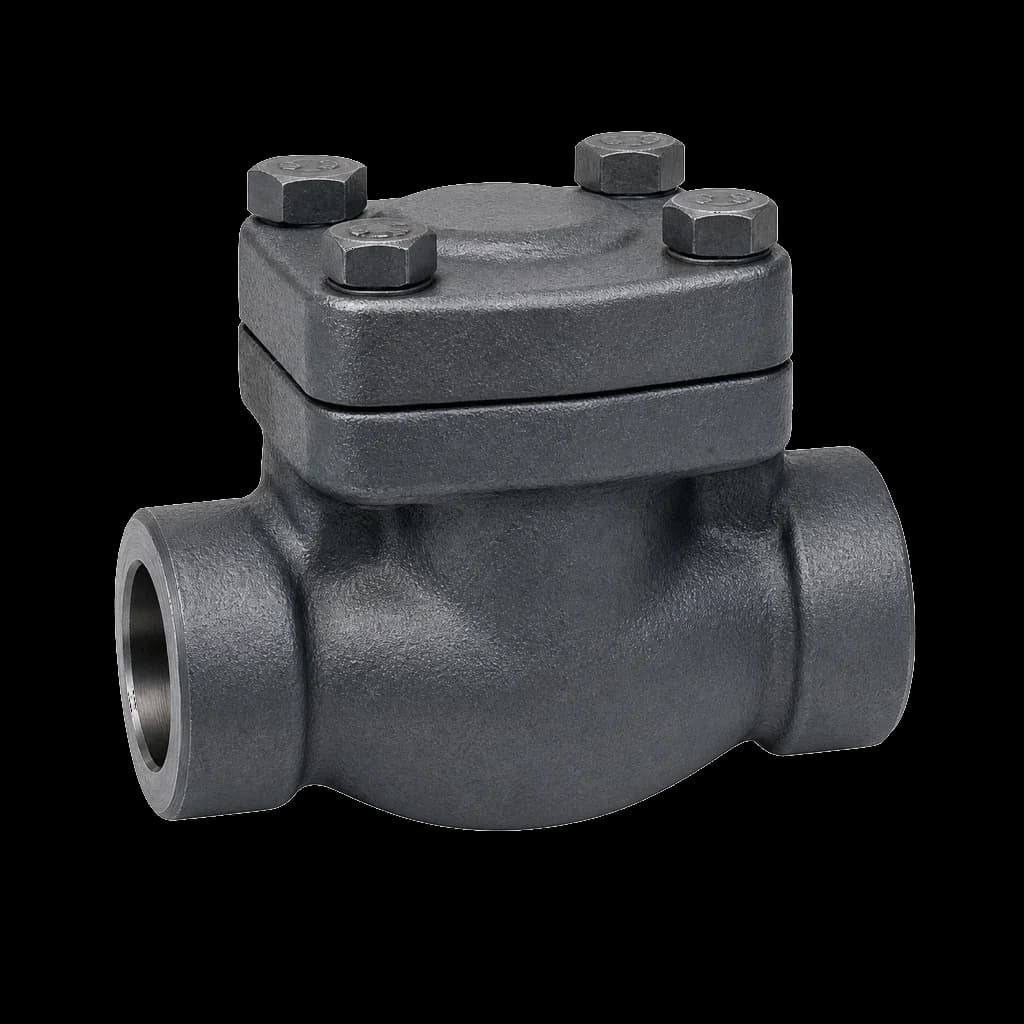
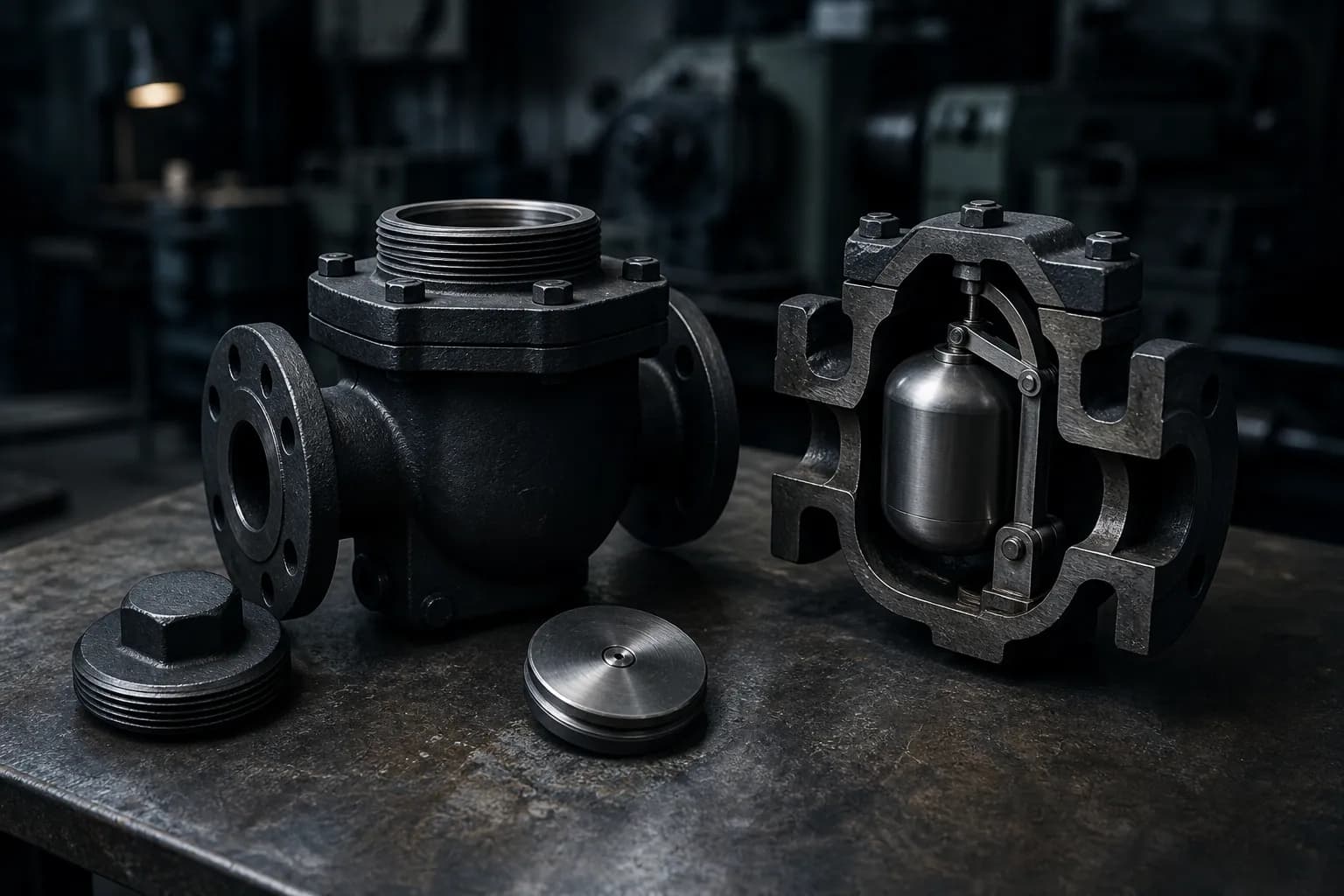
A steam trap is the one component in a steam system that fails without announcing it. A leaking gate valve makes itself heard; a trap that has blown through only makes the condensate return a little hotter and the boiler a little hungrier, and nobody notices for two years. Diagnosis starts with knowing which of the types of steam trap you are looking at, because each family fails in its own direction — thermodynamic discs blow through, float traps waterlog, inverted buckets lose their prime.
The three jobs a trap does at once
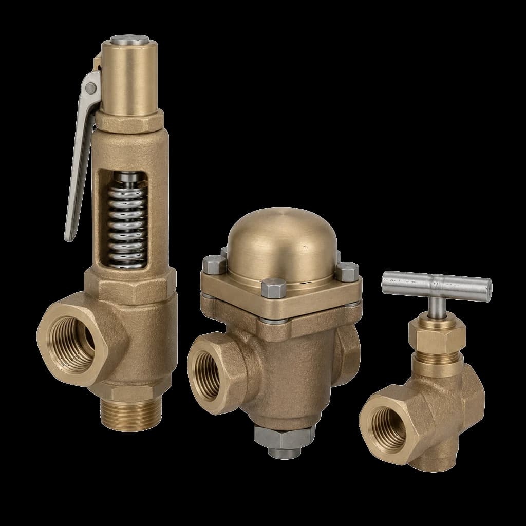
Whatever the mechanism, a trap must discharge condensate as fast as it forms, hold back live steam, and vent air and non-condensables. The three classic fault names map onto those jobs: blow-through fails to hold steam, waterlogging fails to pass condensate, air binding fails to vent. No trap performs better than the station around it — isolation, strainer, drain pocket and return pressure all decide whether it can work. Our steam service valves guide covers the valve side of that station.
The types of steam trap and how each one fails
Traps are classified by the property they sense. Three families cover the five designs you meet in an Indian plant, and the family predicts the failure direction.
Mechanical traps sense density
A float and thermostatic (FT) trap carries a ball float on a lever over a submerged orifice, plus a thermostatic capsule to vent air. Discharge is continuous and modulating, which suits process exchangers, calorifiers and any duty with a swinging load or low differential. Its weakness is mechanical: waterhammer collapses the hollow float, which sinks and stays shut. FT traps fail closed.
An inverted bucket (IB) trap uses the same density principle but needs a water seal — a prime — inside the body. It tolerates dirt and hammer. Lose the prime to an upstream pressure crash or to superheat, and the bucket falls and the valve stays open. IB traps fail open, and they vent air slowly through one hole in the bucket.
Thermostatic traps sense temperature
Balanced-pressure traps use a bellows capsule charged with a water-alcohol mixture that boils just below the saturation temperature around it, so the element tracks line pressure automatically. It opens only after the condensate sub-cools a few degrees, holding condensate back by design — right for tracing and small loads, wrong for an exchanger that must run dry. Bimetallic traps work over a wider sub-cooling band: robust on long tracers, but discharge temperature drifts with back pressure. Both vent air well.
Thermodynamic traps sense flash steam
The thermodynamic (TD) disc trap has one moving part. Condensate lifts the disc; when it flashes underneath, the fast flash snaps the disc down and the pressure held above keeps it shut until it condenses — hence the blast discharge and the audible click. TD traps take superheat, hammer and freezing across a wide pressure range — the default at steam main drip points. Two limits: they need a minimum differential to cycle, and back pressure above roughly 80 percent of the upstream pressure stops them cycling altogether. Never lag a TD trap: insulation keeps the control chamber hot, the disc stays shut, and a healthy trap waterlogs its own drip leg.
| Design | Senses | Best duty | Tends to fail | Air venting |
|---|---|---|---|---|
| Thermodynamic disc | Flash steam velocity | Main drips, tracing, superheat | Open — disc and seat wear | Poor |
| Inverted bucket | Density, needs a prime | Dirty steam, hammer-prone drips | Open — prime lost | Slow |
| Float and thermostatic | Density plus air vent | Modulating exchangers, low differential | Closed — float collapsed | Excellent |
| Balanced-pressure thermostatic | Sub-cooling | Tracing, small loads, air venting | Open — capsule ruptured | Excellent |
| Bimetallic thermostatic | Sub-cooling, wide band | Long tracers, freeze-prone lines | Open — bimetal stack fatigues | Good |
Blow-through: the trap that fails open
A blown-through trap passes live steam into the condensate system while the plant keeps running. Latent heat leaves through the receiver vent, the extra flash lifts back pressure across the whole return network and pushes neighbouring traps towards waterlogging. The tell is a return main hot right to the receiver.
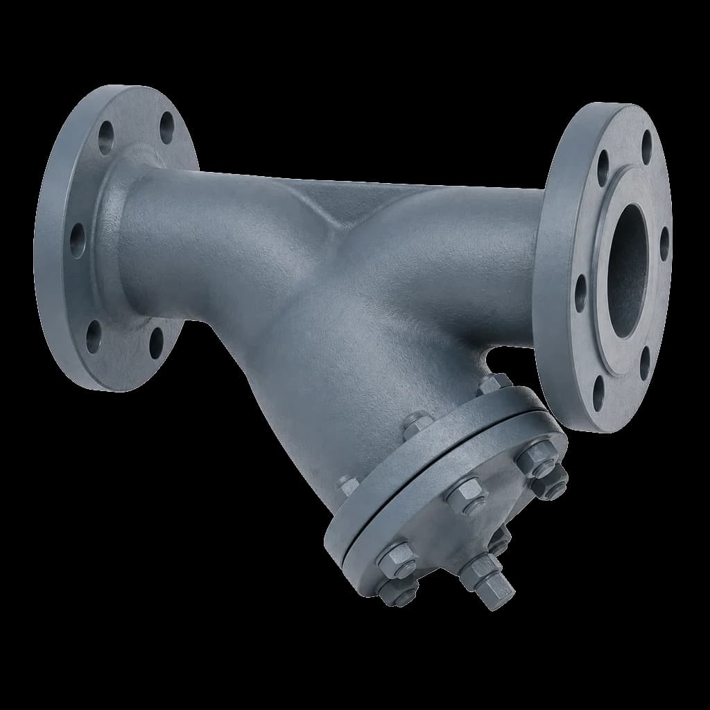
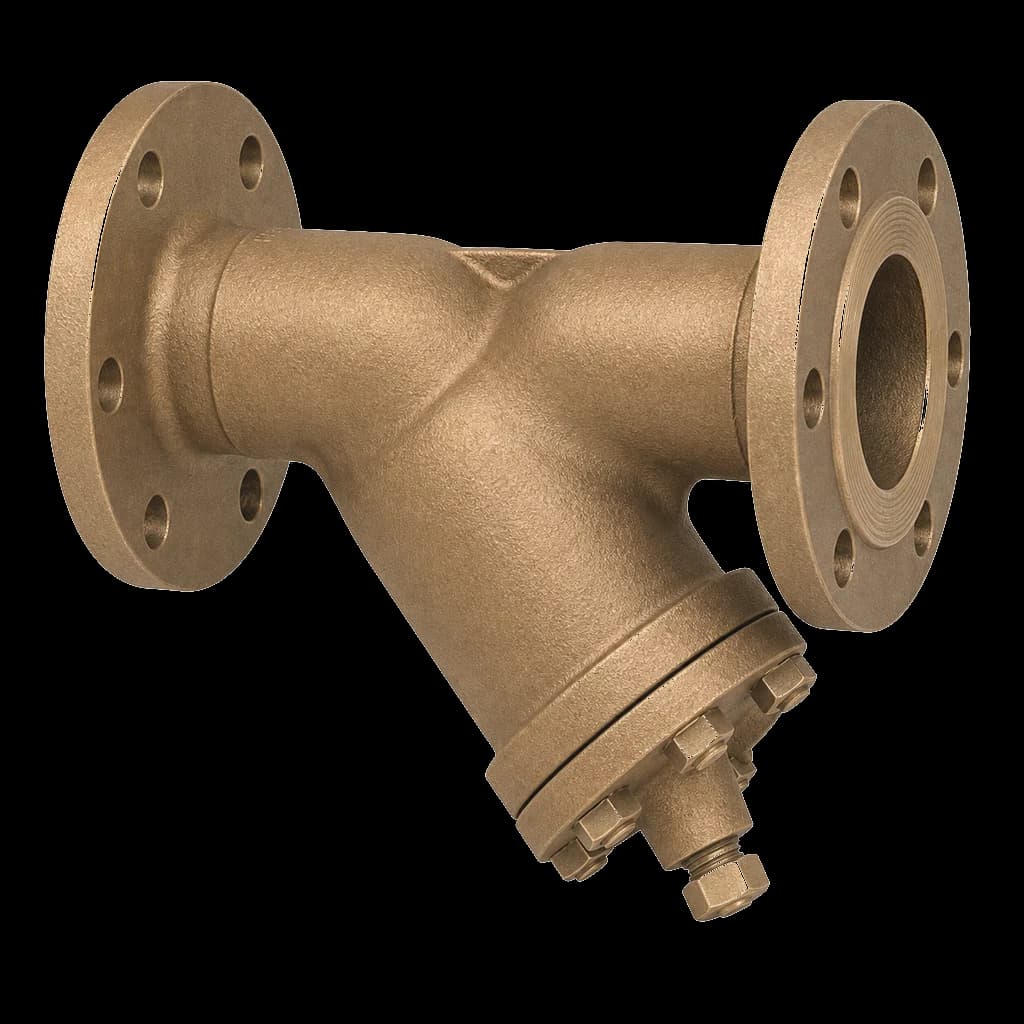
- Dirt on the seat is the commonest cause by far — one scale flake holds the valve open and it never shuts again. A Y-strainer immediately upstream is not optional; our Y-strainer sizing guide covers screen selection.
- Wire-drawn seats. Wet steam across a nearly-closed seat grooves the face; once a TD disc and seat are grooved, only a new set restores shutoff.
- Lost prime or ruptured capsule — an inverted bucket after a pressure crash, a thermostatic element split by hammer or superheat.
- Oversizing. A trap two sizes too large cycles hard and hammers its own seat — not a safety margin.
Waterlogging: condensate that never leaves the equipment
Waterlogging is felt immediately. A jacketed vessel will not reach batch temperature, and heat transfer area disappears under the water line. Standing condensate corrodes too — carbonic acid attacks the bundle and the return lines — and the slugs it throws produce the hammer that kills the next trap.
- Failed closed trap — collapsed float, jammed bucket, blocked orifice.
- Choked strainer. Blow it down before condemning the trap; on a new line the screen fills with mill scale within days.
- Wrong trap for the differential. A TD trap below its minimum working differential simply sits shut — the standard mistake on a temperature-controlled exchanger.
- Back pressure. Every metre of lift after the trap adds roughly 0.1 bar, and a flooded return main adds more. Subtract it before sizing.
- Group trapping. One trap on several units drains the one at the highest pressure and waterlogs the rest. One drain point, one trap.
Stall is not a trap fault
On any exchanger with a modulating control valve, steam-space pressure falls with the load. Once it drops below the return-line pressure the differential reverses and no trap will drain the vessel. That is stall: a system condition, not a defective trap. The cure is a vented drain plus a pump, or a pump-trap — never a bigger trap. If an exchanger drains at full load and floods at part load, stop changing traps and draw the stall chart.
Air binding, steam locking and cold start-ups
At start-up the steam space is full of air, and steam drives it ahead to the coldest point — the drain point where the trap sits. An air-steam mixture sits well below the saturation temperature its total pressure implies, so the plant runs cold while the gauge reads normal. A slow-venting trap, an inverted bucket above all, holds that condition for hours. Fit a trap that genuinely vents, or a thermostatic air vent at the top of the steam space.
Steam locking is the related fault: a long horizontal run between drain point and float trap fills with steam that holds the float up while condensate sits behind it. Close-couple the trap or specify a steam lock release needle.
Diagnosing a trap without shutting the plant down
Temperature alone will not convict a trap: a healthy trap discharges condensate that flashes on the low-pressure side, so a hot downstream pipe proves nothing. Use temperature to find a cold trap, and ultrasound or an open discharge test to find a passing one.
| What you observe | Most likely cause | How to confirm |
|---|---|---|
| Return main hot to the receiver, vent plumes | Traps blowing through | Ultrasonic listening; isolate suspects one by one |
| Disc trap clicking almost continuously | Worn disc and seat on a TD trap | Count cycles against the maker's rate |
| Exchanger will not hold temperature at full load | Waterlogging, choked strainer or stall | Measure the differential; blow the strainer down |
| Trap body cold, line hammering | Failed closed, or strainer packed with scale | Compare inlet temperature with saturation for the line pressure |
Ultrasound separates the two: a healthy intermittent trap gives distinct blast-and-silence cycles, a blow-through a continuous rush. The open discharge test settles it — steady condensate with a lazy plume of flash is healthy, a hard continuous jet is not.
The trap station: where most failures are built in
More traps are killed by the pipework around them than by their own mechanism. A complete station on a steam main drip point reads, in order:
- Drain pocket off the bottom of the main, full line size to about DN100 and at least half line size above — at every low point, rise and control valve, and every 30 to 50 m of run.
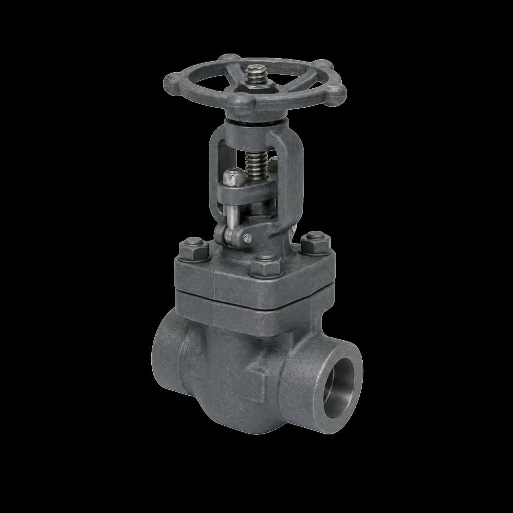
- Upstream isolation — a compact forged gate valve in the header's class, so the trap can be pulled without dropping the line.
- **Y-strainer with a blowdown valve**, screen pocket horizontal and never pointing down — a vertical pocket on steam fills with condensate and hammers.
- Check valve at the discharge into a common return, so a live branch cannot back into an idle one.
- Sight glass or test valve, downstream isolation and a union, so the next survey is not guesswork and the element can be swapped without cutting pipe.
Never lift the discharge of a trap that has no differential to spare: add the static head to the back pressure and re-size first.
Specifying the replacement trap
A trap replaced like-for-like off the old tag plate repeats whatever mistake was made the first time. Rebuild the specification from the duty and send it with the enquiry — the same discipline as our guide to common valve procurement mistakes.
- Maximum working pressure and the actual differential across the trap, not the boiler pressure. Include return-line back pressure.
- Condensate load in kg/h at running condition, plus the start-up load separately and the maker's safety factor — start-up load on a cold main is several times running load.
- Steam condition — saturated, wet or superheated. Superheat rules out several designs outright.
- Body material and end connection — carbon steel, stainless or gunmetal; screwed, socket weld or flanged, with the rating.
- A separator upstream, which strips entrained moisture from wet steam and cuts the trap's condensate load. On a system that eats traps it is often the real fix.
- IBR scope. On boiler-connected steam piping the station's valves and fittings fall under the Indian Boiler Regulations and must arrive certified — see what IBR Form III-C covers.