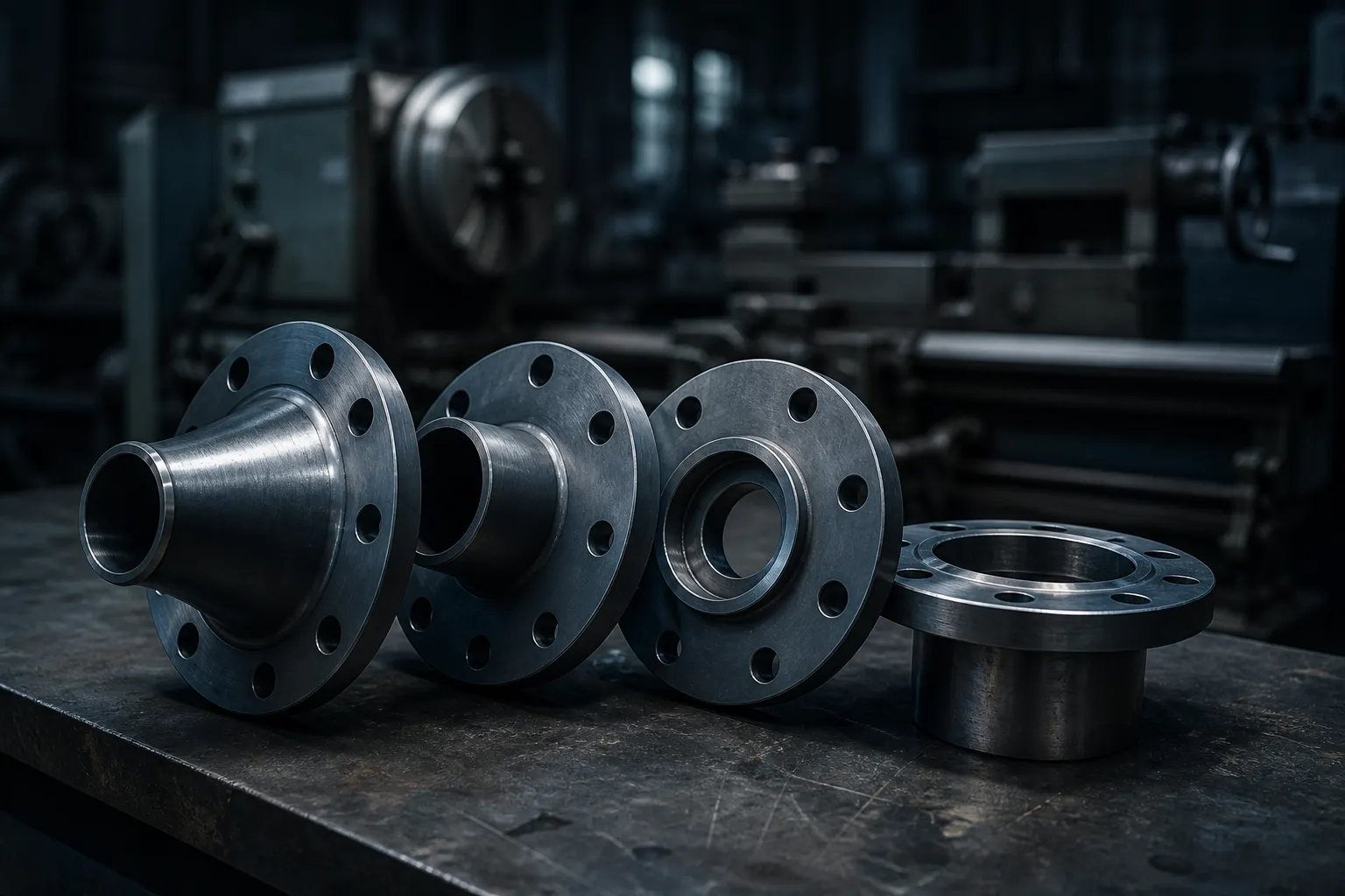
A line spec names four types of flange far more often than all the rest put together: weld neck, slip-on, socket weld and lap joint. They bolt to the same drilling, take the same studs and the same gasket, and to a purchase officer reading a BOQ they look interchangeable. They are not. The choice decides whether the joint can be radiographed, how it behaves under thermal cycling, how much fit-up time the fabricator burns, and — in the lap joint case — how much stainless steel you have to buy. Get it wrong and nothing shows up at hydrotest; it shows up two monsoons later as a crack at a fillet weld, or as a shop variation claim because the flange bore does not match the pipe.
The four types of flange, side by side
All four sit in ASME B16.5, which runs NPS 1/2 to NPS 24 — but they do not all run its full range: socket welding flanges are listed only in the small sizes. Above NPS 24 the joint moves to ASME B16.47 Series A or Series B, where the weld neck is the practical choice; the split between those two series is its own trap, covered in ASME B16.5 vs B16.47. What follows is what separates the four at the joint.
Weld neck (WNRF)
A long tapered hub, butt-welded to the pipe. The taper is machined to match the pipe wall, so the section changes gradually and the discontinuity stress at the joint is low. Two consequences follow. First, a weld neck carries a stress intensification factor of 1.0 — B31's way of saying the joint is as good as the pipe, which is why cyclic, hot and high-class lines are almost always weld neck. Second, the weld is a full-penetration butt weld, so it can be radiographed or ultrasonically examined. The price of that is precision: you must declare the bore, which means declaring the pipe schedule. A Class 300 NPS 6 weld neck in Sch 40 and the same flange in Sch 80 are different items, and ordering the wrong one wastes the flange. If schedule notation is not second nature on your team, read pipe schedules explained before the enquiry goes out.
Slip-on (SORF)
The pipe slides into a counterbore sized to the pipe outside diameter and is fillet welded twice — once outside the hub, once inside the bore, with the pipe end set back from the face so the internal fillet never encroaches on the gasket seating surface. Because the counterbore follows OD, the same slip-on suits Sch 20, Sch 40 or Sch 80 pipe; there is no bore to specify and no cut length to hit exactly. That tolerance is the whole commercial argument. On a firewater header being fabricated at site, or a CPWD water job where the pipe is cut with a grinder and levelled by eye, a slip-on saves more in labour than a weld neck saves in metal. What you give up is inspectability and fatigue life.
Socket weld (SWRF)
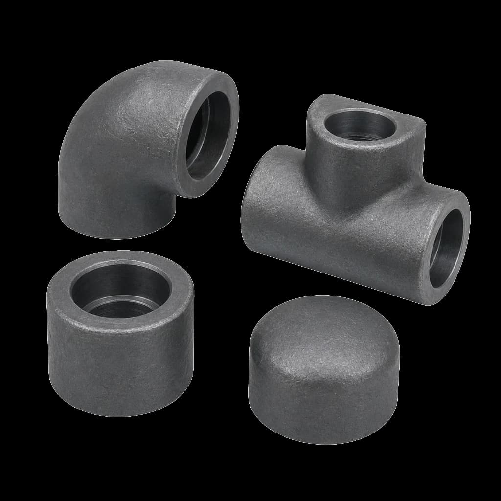
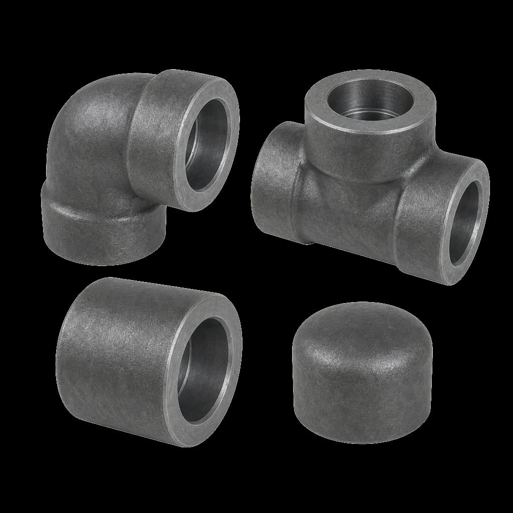
Small bore only. The pipe drops into a machined socket, is withdrawn 1.6 mm (1/16 in) off the shoulder to leave room for weld shrinkage and thermal expansion, and is closed with a single external fillet weld. ASME B16.5 lists socket welding flanges only up to NPS 3, and most refinery and power specs stop them at NPS 2, handing everything larger to a weld neck. They pair naturally with Class 3000/6000 forged fittings on the same hook-up, and the gap rule applies to both.
Lap joint with stub end
Two pieces. A stub end is butt-welded to the pipe and carries the gasket on its lap face; a backing flange slips over the pipe behind the lap and never touches the fluid. Long-pattern stub ends are made to ASME B16.9, the shorter, lighter pattern to MSS SP-43. Because the backing flange is loose, it rotates freely until the studs go in — which is why lap joints survive on large-bore lines where bolt holes never quite straddle the centreline, and on GRP, rubber-lined and glass-lined runs that are dismantled repeatedly.
Welding, NDE and what an inspector can actually prove
| What differs | Weld neck | Slip-on | Socket weld | Lap joint + stub end |
|---|---|---|---|---|
| Weld detail | One full-penetration butt weld | Two fillet welds — outside hub and bore | One external fillet weld, 1.6 mm gap | Butt weld to the stub end; flange unwelded |
| Volumetric NDE | RT or UT both possible | Not possible — surface NDE only | Not possible — surface NDE only | RT possible at the stub-end weld |
| Bore to declare | Yes — must match pipe schedule | No — counterbore follows pipe OD | No — socket follows pipe OD | Yes, on the stub end only |
| SIF in the B31 tables | 1.0 — the datum | 1.2, plus a crevice at the bore weld | 1.3 with the correct gap; crevice in the socket | 1.6 — the worst of the four |
| Usual size band | NPS 1/2-24 (B16.5), larger under B16.47 | NPS 1/2-24, low and moderate classes | Small bore, NPS 3 and below | NPS 1/2-24, common on lined and SS lines |
| Buy it when | Hot, cyclic, high class, hydrogen, IBR | Utility water, air, low-class site work | Instrument, drain, vent, sampling hook-ups | Frequent dismantling or mixed materials |
- Fit-up time is the slip-on's real saving. No bevel, no root gap, no root pass, no tolerance to chase — the pipe goes in until it hits the setback. Against that you weld twice instead of once, so in a shop with an automatic process the labour gap narrows sharply.
- A fillet weld cannot be volumetrically examined. If the ITP calls for random radiography on the line class, slip-on and socket weld joints escape it by geometry, not by concession. That is fine on utility water and indefensible on a hydrocarbon or IBR line, and a third-party inspector will say so at the review stage rather than at site.
- Rework costs diverge. Cutting out a defective butt weld costs you the weld. Cutting out a slip-on or socket weld costs you the flange, the pipe end and usually the spool dimension, because the pipe is consumed inside the hub.
- Only the lap joint rotates. Once a weld neck or slip-on is welded, its bolt holes are fixed and must straddle the vertical centreline. A lap joint backing flange can be spun into place at site — the single biggest reason it survives on tank nozzles and large-bore stainless headers.
- Weight and freight. A weld neck is the heaviest of the four at the same size and class. On an export consignment to the Gulf, that difference is real money on the same BOQ.
Where socket welds stop being the right answer
Two limits govern socket weld construction. The first is the crevice: the annular gap between the pipe OD and the socket wall is a dead space that traps chlorides, condensate and solids. In stainless steel handling brackish or chlorinated water, that crevice initiates pitting long before the pipe wall thins anywhere else, and no amount of external weld quality helps. The second is fatigue. ASME B31.3 places explicit restrictions on socket welded joints under severe cyclic conditions, and even outside that definition the fillet weld toe is the first thing to crack on a small-bore line vibrating off a reciprocating compressor. Where vibration is expected, brace the line, go to a butt-welded detail, or accept a weld neck at NPS 2 despite the cost. For the wider trade-off between threaded, grooved and welded construction, see grooved vs threaded vs welded piping. Socket weld flanges and socket weld fittings are still the correct default for instrument tappings, drains, vents and gauge hook-ups — just not for the shaking ones.
Lap joint economics: stainless only where the fluid is
In a stainless line a weld neck flange is a solid forged block of ASTM A182 F304 or F316, and above NPS 6 even a Class 150 flange is a heavy forging in that grade. Switch to a lap joint and only the stub end need be stainless. It is a thin, short component, and it is the only part the fluid touches. The backing flange, which sees nothing but bolt load, can be carbon steel to ASTM A105. On a large-bore stainless header with many flanged breaks, that substitution removes most of the alloy weight from the flange scope while keeping every wetted surface in the specified grade.
The catch list is short but non-negotiable. Rate the joint by its weakest member — confirm the stub end's rating, not just the backing flange's. Protect the carbon steel backing flange: in a coastal plant it corrodes while the stub end does not, so galvanising or coating belongs in the specification. And accept that a lap joint has no ring-type joint variant — the gasket seats on the lap face formed by the stub end, so where the line class calls for RTJ the lap joint is out.
Indian spec practice: IS tables, BS 10 and IBR lines
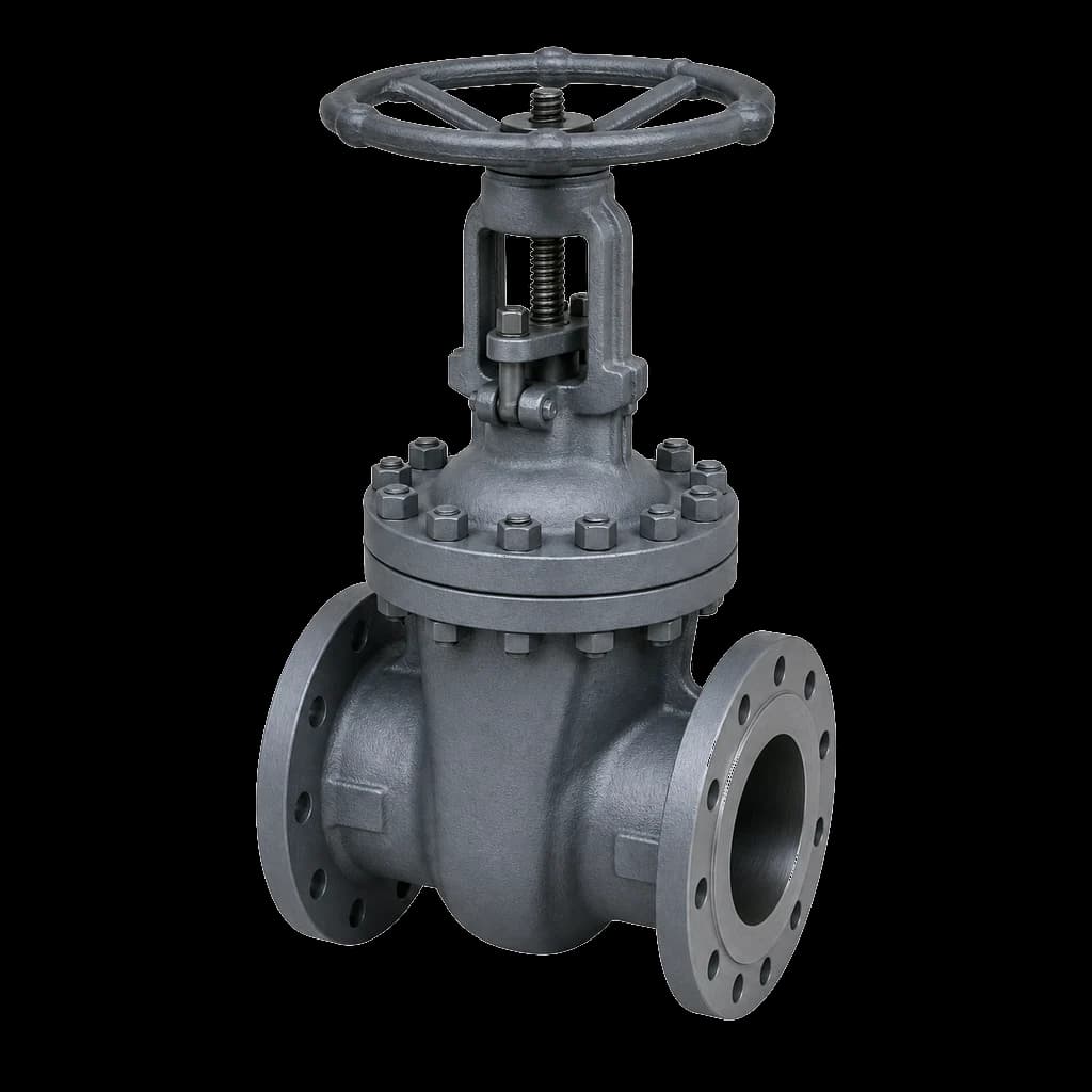
Not every Indian tender speaks ASME. Steel pipe flanges to IS 6392 still appear in PSU and state utility documents, cast iron drilling to IS 1538 governs the companion flanges on CI valves and pump casings, and old water-works and fire tenders continue to call BS 10 Table D, E or F drilling that matches nothing in B16.5. Ask which drilling table applies before quoting a single flange: a Table F flange and a Class 150 flange of the same nominal bore will not bolt together. On cast iron bodies the facing question is settled for you — use a flat face with a full-face gasket, because a raised face concentrates bolt load inside the bolt circle and can crack a brittle CI flange. That applies directly to CI sluice valves on water and firewater duty. On steam under the Indian Boiler Regulations the flange is part of the certified assembly: weld neck construction is expected on boiler external piping, and the documentation trail matters as much as the metal.
Selecting class, facing and type together
Flange type, pressure class and facing are one decision, not three. The table below is where most Indian process and utility jobs land; reconcile it against your line class before it becomes an enquiry. The facing question in detail — raised face height, flat face and ring joint — is covered in RF vs FF vs RTJ facings.
| Service | Typical class | Facing | Flange type that usually wins |
|---|---|---|---|
| Firewater ring main, hydrant risers | Class 150 (or BS 10 Table E/F on legacy tenders) | RF, 1.6 mm raised face | Slip-on |
| CI sluice valves, pump casings, DI mains | PN 1.0 / PN 1.6 or Class 125 drilling | Flat face, full-face gasket | Slip-on or CI companion flange |
| Compressed air, cooling water, plant utility | Class 150 | RF | Slip-on |
| LP steam and condensate outside IBR scope | Class 150-300 | RF | Weld neck |
| IBR steam, boiler external piping | Class 300 and above | RF | Weld neck, with the certification trail |
| Instrument tappings, drains, vents, sampling | Line class flange, 3000/6000 fittings | RF | Socket weld |
| Hydrocarbon process, hot or cyclic duty | Class 300-1500 | RF; RTJ where the line class calls for it | Weld neck |
| Stainless or lined lines dismantled often | Class 150-300 | RF | Lap joint with stub end |
What a complete flange line item says
- Type and facing spelled out: weld neck RF, slip-on RF, socket weld RF, or lap joint with stub end. WNRF and SORF are fine in a BOQ, not as the only description on a drawing.
- Size and class in one system. NPS and Class per ASME B16.5, or DN and PN per the IS/EN route — never NPS with a PN rating in the same line, which is the single most common cause of a rejected flange at the gate.
- Bore or schedule for every weld neck and every stub end. Slip-on and socket weld items do not need it, and asking for it only confuses the quote.
- Material grade in full: ASTM A105 for carbon steel, A182 F304/F316 for stainless, A350 LF2 for low temperature, and state the heat-treated condition if your spec demands it.
- Standard and drilling table: ASME B16.5, B16.47 Series A or B, IS 6392, or the BS 10 table — plus gasket and bolting, which are ordered against that same facing.
- Certification: EN 10204 3.1 as the default, 3.2 where a third-party inspector is nominated, and IBR documentation where the line falls under boiler regulations.