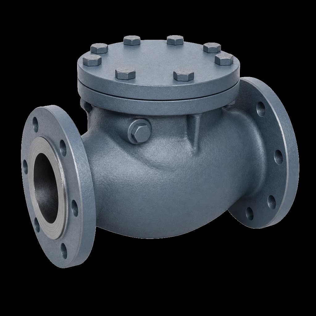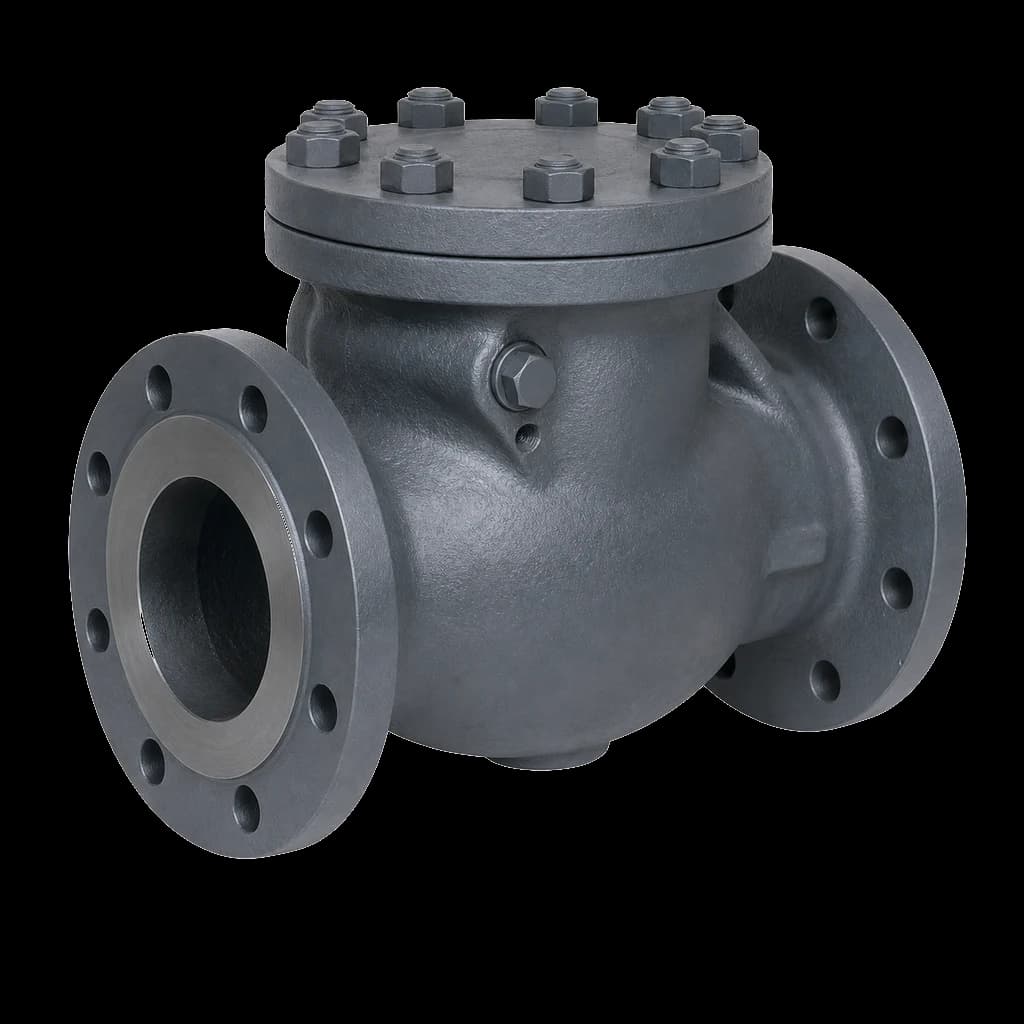
Every pumping station drawing from a sump or an intake well runs the same argument in design review: hang something on the bottom of the suction pipe, or fit a non-return valve on the delivery side and be done with it? The two are not interchangeable. A foot valve for pump suction is a check valve and a strainer in one submerged body, holding the water column in the pipe when the pump stops. A discharge NRV stops reverse flow, but it cannot hold prime on a lift: the moment the pump stops, the suction line drains back through the open bell mouth.
What a foot valve for pump suction actually does
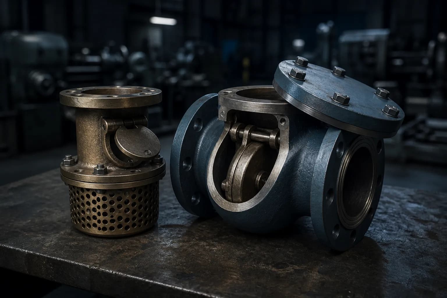
A foot valve is a non-return valve with an integral screen. It does three jobs: it stops the suction column draining back to the sump, keeps weed, leaves, gravel and site debris out of the impeller, and gives priming water somewhere to sit while the casing fills. Delete it from a suction-lift arrangement and you have committed to a priming system — vacuum pump, ejector, priming tank or self-priming casing — that must be powered, maintained and proved.
The priming argument
A centrifugal pump cannot lift air. On a suction lift the casing and the whole suction pipe must be liquid-filled before start, and the foot valve is the simplest device that keeps them filled between runs. It is no substitute for a priming set on a critical duty: a seat sitting in silty water eventually weeps, and a slow leak empties an eight-metre suction line overnight. On unattended or auto-start duties specify the foot valve and an automatic priming device, and treat the valve as a debris screen with a prime-holding bonus.
The screening argument
The screen is usually the only barrier between the sump and the impeller, and what decides whether the pump loses suction is its net open area, not its hole size. Water-works practice asks for at least three times the cross-section of the suction pipe, and four where the water is dirty, so that even half-blinded the approach velocity through the perforations stays low. Where the water carries fibrous matter, a trash rack ahead of the bell mouth beats a finer screen on the valve. It is line-strainer arithmetic, worked through in our guide to pump suction strainer mesh and NPSH.
Suction lift or flooded suction: which arrangement needs what
Most of the confusion on site comes from applying a sump-pump habit to a tank-fed pump: fix the arrangement first, then choose the hardware.
| Suction arrangement | Foot valve | Discharge NRV | Notes |
|---|---|---|---|
| Suction lift from open sump or intake well | Yes, with integral screen | Yes, separate | Foot valve holds prime; NRV stops reverse rotation |
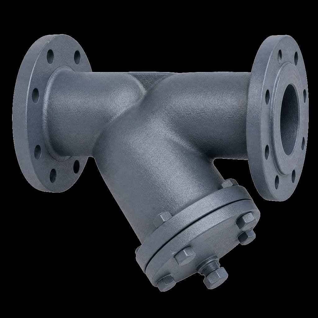
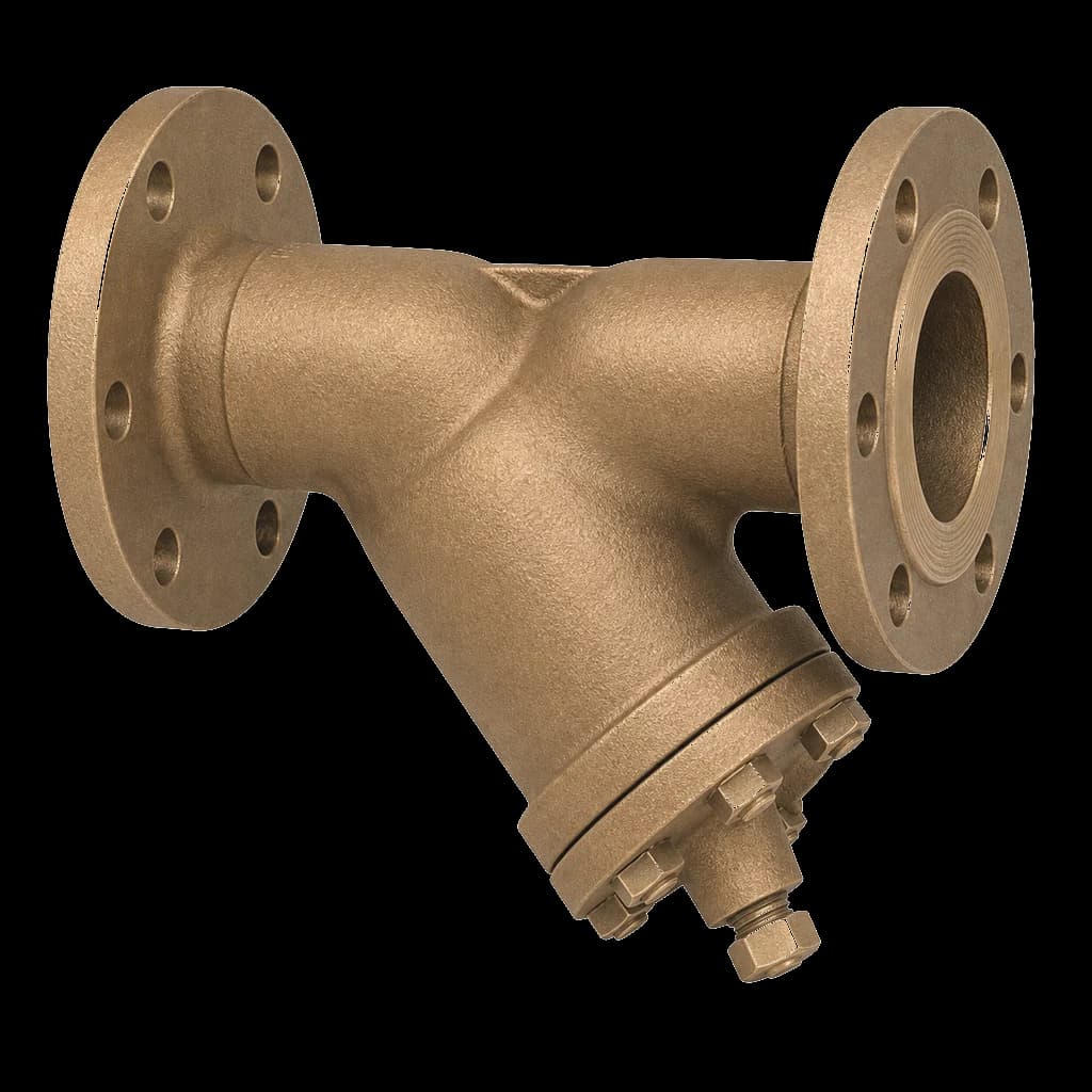
| Flooded suction from overhead or ground tank | Not required | Yes | Use a Y or basket strainer that can be cleaned in place |
| Firewater pump from a static tank | Avoid | Yes | NFPA 20 and Indian practice want positive suction head |
| Self-priming pump on lift | Not needed | Yes | The casing retains the prime; a foot valve only lengthens re-prime |
| Submersible or vertical turbine in a wet well | No | Integral or line NRV | Column stays wetted; the pump's own non-return suffices |
The rule is blunt: a foot valve earns its place only when the pump has to lift. On a flooded suction it adds head loss right at the impeller inlet and leaves one more submerged item nobody can reach without a crane and a de-watered sump.
Types of foot valve and where each one belongs
| Type | Closing element | Grit tolerance | Best fit |
|---|---|---|---|
| Ball type | Free-floating rubber-covered ball, cage-guided | High | Silty sumps, canal and borewell water |
| Flap / hinged disc | Single rubber-faced disc on a pin | Medium | The common cast-iron water-works pattern |
| Multi-door | Several small hinged doors in one body | Medium | Large intakes where one heavy disc would slam |
| Lift / spring-assisted disc | Axial disc, often spring-loaded | Low | Vertical pipe needing fast closure; costs head |
Ball type foot valves suit Indian sump work, because that water is rarely clean. A guided rubber-covered ball rolls off its seat and reseats by gravity, so grit that would score a flat disc-and-seat line rolls aside instead of lodging between sealing faces. The trade-offs are higher head loss and a size ceiling: past medium bore the ball becomes unmanageably heavy and hinged patterns take over. Cast iron to IS 4038, the water-works specification, is the default for municipal and PHED work from 50 mm upward. For the same closing elements in the delivery line, see swing, dual-plate and wafer check valves.
The NPSH penalty you pay at the bottom of the pipe
Everything a foot valve does, it does inside the suction line, so everything it costs comes out of NPSH available. Build that number honestly:
- Barometric head — about 10.3 m of water at sea level, roughly a metre less per 1000 m of elevation. A hill station starts poorer than Kandla.
- Vapour pressure head — negligible for cold water, steep with temperature. Hot well and condensate duties do not belong on a suction lift.
- Static lift — measured to the *lowest* operating water level, not the normal one. On a river intake the pre-monsoon drawdown decides the design.
- Friction and fittings — pipe, bell mouth, bends and the foot valve itself. Ask for a Kv or head-loss curve at your actual flow; the published figure assumes a clean screen.
Subtract the total from the pump's NPSH required and hold a real margin — half a metre is the floor, and many specifications ask a metre or more. If the margin only closes with a new screen at normal water level, the design has already failed: it will cavitate in April when the sump is low and the screen half-blinded. Practical suction lift on cold water rarely works out beyond six to seven metres.
Sizing: the foot valve is not automatically line size
Size the suction line on velocity, not on the pump's suction nozzle. Hold 1.0 to 1.5 m/s, and nearer 1 m/s on WTP and PHED work so friction does not eat the lift budget. The suction pipe is therefore usually a size or two larger than the nozzle, with an eccentric reducer flat side up at the pump — and the foot valve follows the pipe.
Failing in both directions
Undersizing is the obvious error: high velocity through the screen, heavy head loss, and cavitation that shows up as pitted impeller vanes at first overhaul. Oversizing is the quieter one. A hinged disc that never reaches full lift flutters against its stop, wears the pin oval and eventually drops into the sump; an unlifted ball chatters on its seat. Where a VFD turns the pump down, check the closing element at minimum flow as well as rated, and put that figure in the enquiry.
CI, bronze or stainless: matching the body to the water
| Service water | Body | Closing element | Screen |
|---|---|---|---|
| Raw river or municipal water | Grey iron FG 200 to IS 210 | Rubber-faced gunmetal or DI disc | Integral CI or SS 304 |
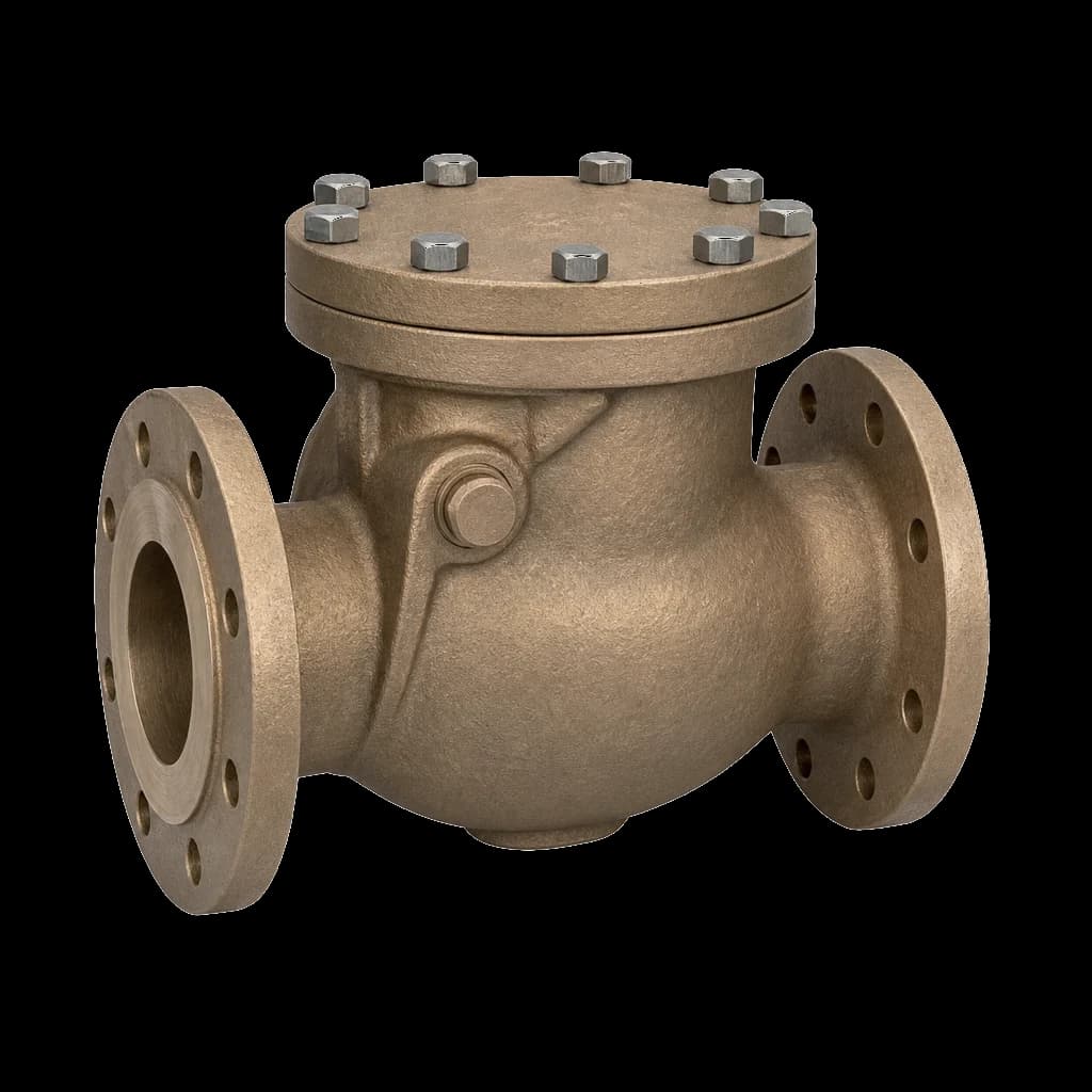
| Brackish or high-chloride intake | Leaded tin bronze LTB 2 to IS 318 | Bronze with nitrile facing | SS 316 perforated |
| DM water, dosing, food-contact duty | CF8M / SS 316 castings | SS 316 disc, EPDM or PTFE seat | SS 316 perforated |
| Sandy borewell, canal or silty sump | Ductile iron to IS 1865 or heavy CI | Rubber-covered guided ball | Coarse, generous open area |
Two things get specified badly here. Coating first: a submerged body spends its life wet, so ask for fusion-bonded epoxy to a stated thickness inside and out, not yard-applied bitumen. Fasteners second — cover bolts, hinge pins and cage screws in stainless, because a bronze valve hung on carbon-steel pins is a bronze valve that seizes. On a chloride-bearing intake, bronze and stainless outlast cast iron by enough to change the whole-life sum even though the CI valve is cheaper.
Fire pumps, WTP headworks and what the tender asks
For firewater the answer is usually no foot valve at all. NFPA 20 and Indian insurance practice want the pump under positive suction head from a static tank, so the tank holds the prime rather than a rubber-faced disc in a sump. Where a lift is unavoidable — an open reservoir, a canal-fed intake — the foot valve becomes a safety-critical item on a documented weekly churn test, not a fit-and-forget fitting. Our fire fighting valves guide covers the rest of that package.
Intake wells, jackwells and backwash sumps at a water treatment plant are where cast-iron foot valves belong, specified to IS 4038 alongside sluice valves to IS 14846 and reflux valves to IS 5312. Municipal and PHED tenders ask for BIS-marked castings, a hydrostatic test certificate for body and seat, and a material certificate — agree all of it before despatch, not at the gate. If the tender is silent on screen open area, write your own figure into the technical schedule; leave it to the vendor and a well-coated valve arrives with a screen that blinds in the first monsoon.
How foot valves fail, and what to write into the spec
- Overnight leak-back. A seat passing a few drops a minute empties a long suction line by morning. Specify seat tightness, and design the priming arrangement as though the valve will pass.
- Blinded screen. Weed and silt eat the free area long before the perforations block. Ask for open area as a multiple of pipe bore, and provide a way to lift and wash the valve.
- Seized or worn hinge pin. Stainless pins and bushes, checked at every overhaul. A dropped disc in the sump is a rebuild, not a repair.
- Slam on shutdown. A large single disc closing against a returning column is a water-hammer source; multi-door patterns and a well-chosen delivery non-return tame it — see reflux valve slam and water hammer.
- No retrieval route. A valve reachable only by de-watering the sump never gets cleaned. Provide a removable spool, a lifting eye and a chain to the deck at design stage.
The specification that buys a good foot valve is short: arrangement, bore, body and trim material, screen open area, seat tightness, coating, test and certification. Everything past that is the vendor's problem.